Reflow Toaster Oven - a Qwiic Hack!
Grab some parts, strap a servo on it, and you'll be reflowing solder in no time!

While working from home during the past few months, I have greatly missed being able to throw some prototypes through the super nice SparkFun production reflow oven.
Ahhh, so glad I didn't have to hand solder each of those blobs.
I really wanted a reflow oven in my garage, so after doing some research online, I decided to buy a cheap toaster oven and give this hack a try. Ultimately, I decided to use a standard hobby servo to automate the movement of the temperature knob like so:
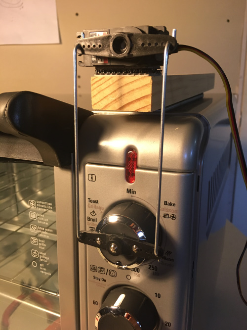
Just like a push-pull linkage in a model airplane!
Although slightly less elegant than some of the other methods out there, this servo control method works quite well. Additionally, it didn't require any modifications to the wiring of my toaster oven and was pretty darn cheap and simple to setup.
Research
I came across many blogs, websites and products dedicated to hacking toaster ovens into reflow ovens:
- SparkFun Reflow Toaster Tutorial (2006)
- SparkFun Reflow Toaster Controller (retired product from 2007)
- X-Toaster Article - choosing an oven
- CompuPhase Article - understanding reflow profiles
The most important things I learned were the following:
Get a toaster oven with these features (I purchased the Black & Decker TO3000G, which was $59 new):
- Analog dial control style
- Quartz elements (two above and two below if you can)
- Convection type oven that includes internal fan. This really helps reduce temperature variations within the oven. When shopping, look for the word "convection" in the name.
- Small or medium-sized
A single thermocouple "floating" in the air near the PCB works fine. Note, a lot of the pro-end models have multiple temp sensors (at multiple points in the chamber and one touching the PCB), but I haven't found the need yet. The SparkFun Qwiic Thermocouple and braided thermocouple work great!
Opening the door seems to be the only way to get a good and fast cool down. Even the ~$4,000 pro machines have the drawer open automatically to achieve good "free air" cooling. I have yet to automate this step, but so far I love watching the solder flow. When I see my reflow time is up, I have been manually opening the door. If I find the need to automate this in the future, I'll most likely get another servo or stepper motor involved.
Most toaster ovens can't achieve an ideal ramp up rate of 1.5C/second, but that's okay. You can add a slower ramp up during your soak phase - a slow ramp up from 150-180. More on this later as we discuss the profile, the code and show some results.
Parts List
- Redboard Artemis
- SparkFun Qwiic Thermocouple Amplifier - MCP9600 (Screw Terminals)
- Thermocouple Type-K - Glass Braid Insulated (Bare Wire)
- Qwiic Cable - 100mm
- Servo - Hitec HS-422 (Standard Size)
- USB-C Wall Adapter - 5.1V, 3A (Black)
- Reversible USB A to C Cable - 2m
- Solder Paste - 50g (Lead Free)
- 3M Dual Lock (or servo tape)
- Control Rods - find at your local hobby or hardware shop
- Two large servo horns (you should get some with your servo, but may need to get a second one)
Manual testing
Before rigging up a servo to move the control knob, I first gathered parts and got my thermocouple readings working. Then the plan was to simply move the control knob manually (with my hand), and see if I could get a decent profile while watching the data plotter.
My very first attempt manually adjusting the knob by hand.
Following the profile suggestions in the CompuPhase article and reading what Wikipedea had, I decided to try for a profile represented by the blue line in the graphic above. The red represents the live readings from the thermocouple. Note: in all of my serial plotter graphics, the blue line is being plotted as a reference, and my controller is not analyzing the blue line in any way.
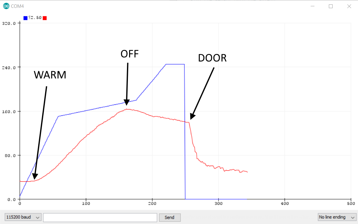
And so I tried again:
Second attempt adjusting temp knob by hand.
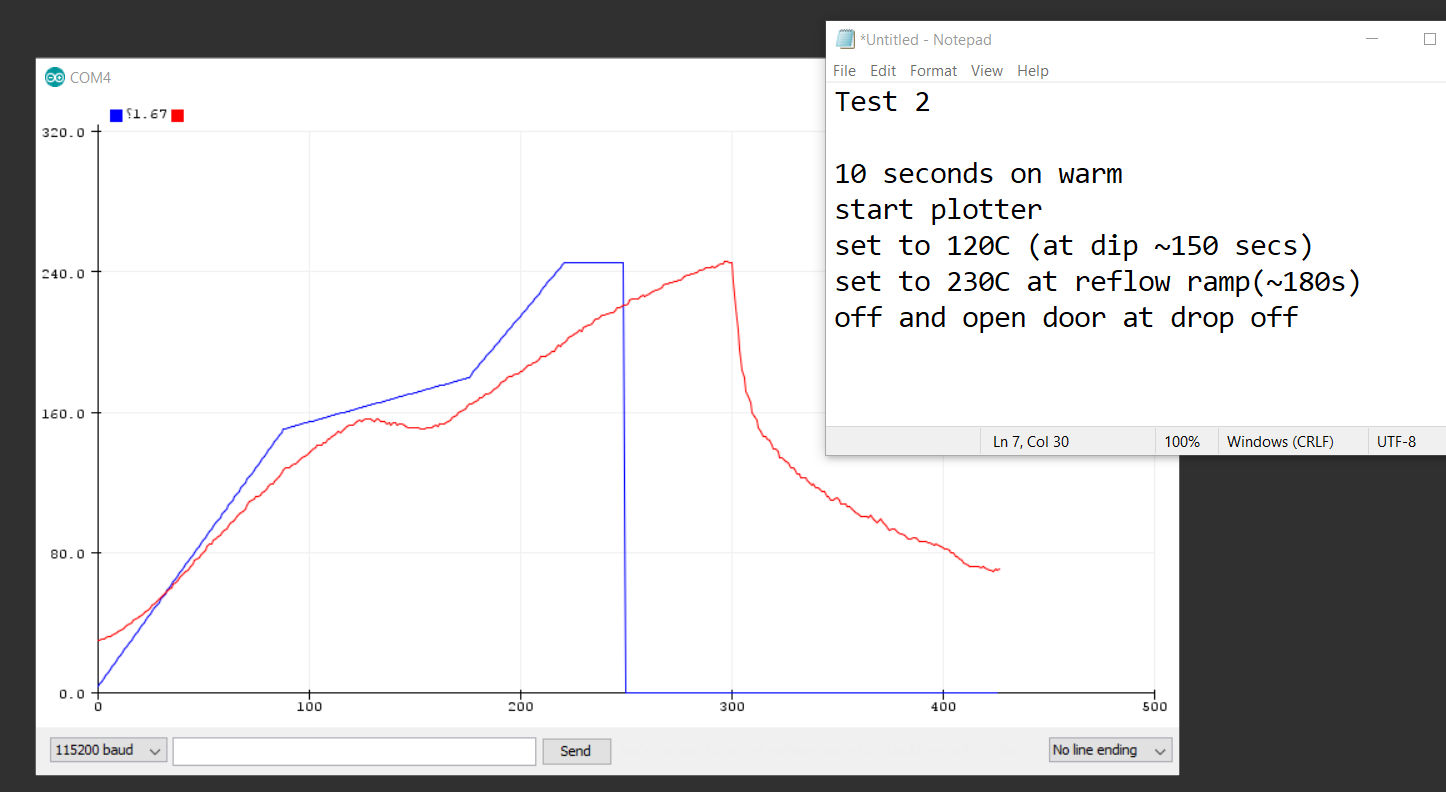
As you can see, I started taking notes to keep track of what was working and what was not. For my second attempt, I actually set the oven to "warm" for ten seconds before starting my plotter. The adjustments noted in the graphic were done by me physically moving the dial with my hand.
By my fourth manual test, I was pretty pleased with the results - not perfect by any means, but starting to look a bit like an actual profile:
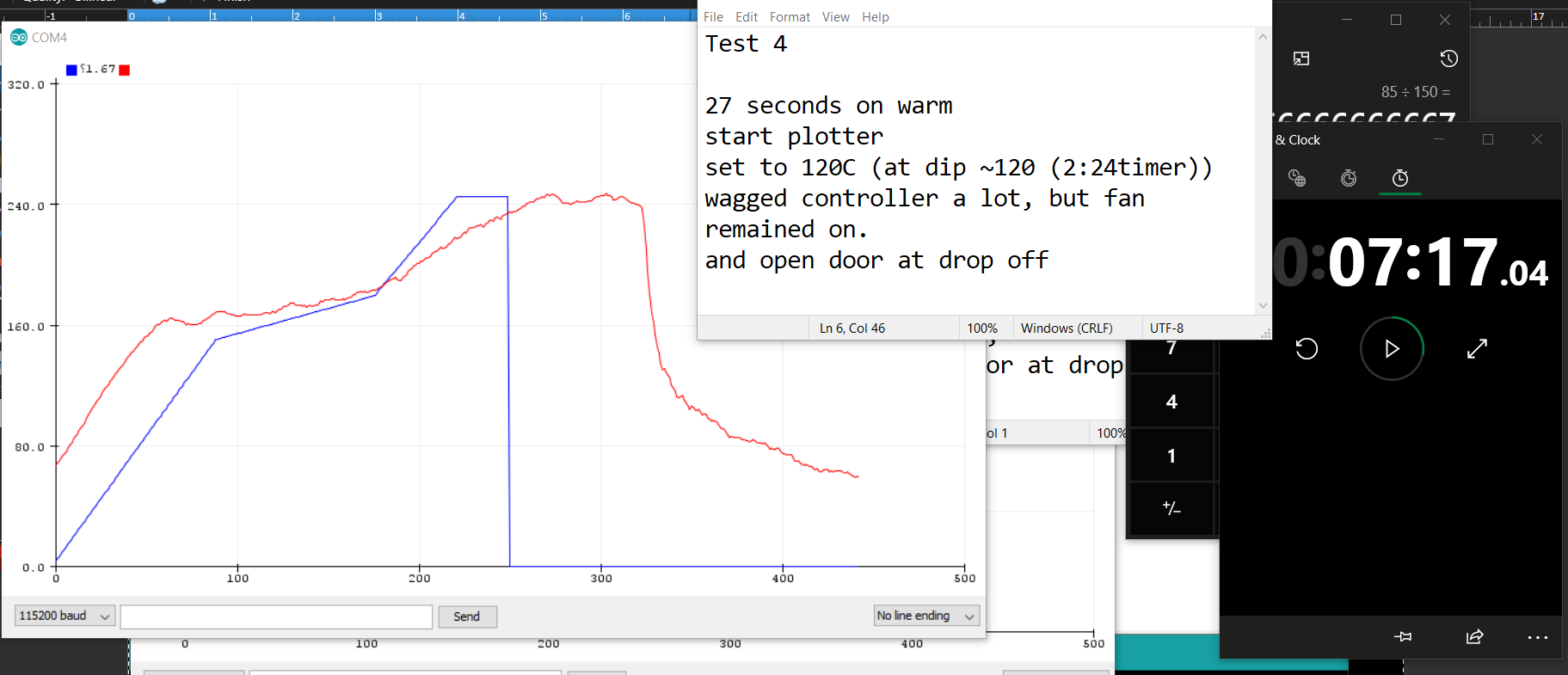
Fourth attempt by hand, starting to look decent.
Servo Hack
Now that I knew a decent profile could be achieved by simply moving the temp dial, it was time to slap a servo on this thing and automate the movements!
First things first, I ripped off that control knob. A flat head screw driver helped greatly to get it started. Next, I mounted the servo horn to the knob with a servo mount screw in the center hole of the servo horn.
 |
 |
| Temp knob removed. | Mount with center point screw first. |
Then, I drilled out two more holes for a good secure mount. Note: I'd make sure to align the positioning mark (that little silver thing) directly down. This will ensure that the servo linkage and rotation can achieve the full 180 degrees of motion.
 |
 |
| Mounted servo horn with center screw. | Horn mounting complete. |
Next was actually mounting the servo to the oven. I had a scrap piece of wood that fit the job exactly, but anything that can extend the servo out past the face of the oven should work. I opted to use dual-lock hook and loop, but servo tape or double-sided foam tape would have worked too. Make sure to align properly both along the center point of the servo horns and the depth away from the oven.
 |
 |
| Center point alignment. | Depth alignement. |
Finally, the last step was to link the two control horns. There are many ways to do this with various linkage hardware, but the simplest is to use bare control rods and add "Z-bends" at specific points. I first tried this with a single control rod, but it was much smoother with two!
 |
 |
| Z-bend | Dual control rod hooked up |
The Code
The source code for the project can be downloaded from the GitHub repository here:
Using Example 1 from the Qwiic Thermocouple Arduino Library and a basic servo control example, I was able to piece together a sketch that accomplishes a pretty nice reflow profile.
Before diving into the code, I'd like to highlight the fact that this project does not use PID control to try and follow a set profile. I first proved out that manually moving the temp knob by hand could create a decent reflow profile. By watching the temperature and keeping track of time, my Arduino can determine the zone (preheat, soak, ramp up, reflow, cooldown). Once you know the zone, you can simply set servo to predetermined positions (or toggle on/off as in soak) to hold a close enough temperature or ramp up.
My plan was:
- Set full power
- Wait to see 140C, kill power, enter soak zone
- During soak, toggle power on/off to climb from 150C to 180C
- Once soak time is complete, turn on full power (enter ramp-up zone)
- During ramp-up, wait to see reflow temp (220C) (enter reflow zone)
- During reflow, toggle servo on/off to hold temp
- Once reflow time is complete, turn servo to "off," indicating user should open door
My main loop simply uses a "for loop" to get through the zones, then when it's done it stops with a "while(1)". It is updateServoPos() that actually determines the zone and updates a global variable.
void loop() {

for (int i = 0 ; i <= 4 ; i++) // cycle through all zones - 0 through 4.
{
    int tempDelta = abs(profileTemp[i + 1] - profileTemp[i]);
    int timeDelta = abs(profileTimeStamp[i + 1] - profileTimeStamp[i]);
    float rampIncrementVal = float(tempDelta) / float(timeDelta);
    currentTargetTemp = profileTemp[i];

    // Print data to serial for good plotter view in real time.
    // Print target (for visual reference only), currentTemp, ovenSetting (aka servo pos), zone
    for (int j = 0 ; j < (timeDelta - 1); j++)
    {
    currentTargetTemp += rampIncrementVal;
    Serial.print(currentTargetTemp, 2);
    Serial.print(",");

    if (tempSensor.available())
    {
        currentTemp = tempSensor.getThermocoupleTemp();
    }
    else {
        currentTemp = 0; // error
    }

    Serial.print(currentTemp);
    Serial.print(",");

    updateServoPos(); // Note, this will increment the zone when specific times or temps are reached.

    Serial.print(ovenSetting);
    Serial.print(",");

    Serial.println(zone * 20);
    delay(1000);
    totalTime++;
    }
}

// monitor actual temps during cooldown
for (int i = 0 ; i < COOL_DOWN_SECONDS ; i++)
{
    currentTargetTemp = 0;
    Serial.print(currentTargetTemp, 2);
    Serial.print(",");
    if (tempSensor.available())
    {
    currentTemp = tempSensor.getThermocoupleTemp();
    }
    else {
    currentTemp = 0; // error
    }
    Serial.print(currentTemp);
    Serial.print(",");
    updateServoPos();
    Serial.print(ovenSetting);
    Serial.print(",");
    Serial.println(zone * 20);
    delay(1000);
}
while (1); // end
}
The following function, updateServoPos(), is where the temperature and totalTime is checked to determine the zone we are currently in, and ultimately what servo positions are desired.
void updateServoPos()
{
    if ((zone == ZONE_preheat) && (currentTemp > 140)) // done with preheat, move onto soak
    {
        zone = ZONE_soak;
    }
    else if ((zone == ZONE_soak) && (soakSeconds > SOAK_TIME)) // done with soak, move onto ramp
    {
        zone = ZONE_ramp;
    }
    else if ((zone == ZONE_ramp) && (currentTemp > 215)) // done with ramp move onto reflow
    {
        zone = ZONE_reflow;
    }
    else if ((zone == ZONE_reflow) && (reflowSeconds > 30))
    {
        zone = ZONE_cool;
    }

switch (zone) {
    case ZONE_preheat:
        setServo(41);
        break;
    case ZONE_soak:
        soakSeconds++;
        if ((soakSeconds % 15) == 0) // every 15 seconds toggle
        {
            soakState = !soakState;
        }
        if (soakState)
        {
            setServo(100);
        }
        else {
            setServo(0);
        }
        break;
    case ZONE_ramp:
        setServo(100);
        break;
    case ZONE_reflow:
        reflowSeconds++;
        if ((reflowSeconds > 5) && (reflowSeconds < 10)) // from 5-10 seconds drop to off
        {
            setServo(0);
        }
        else {
            setServo(100);
        }
        break;
    case ZONE_cool:
        setServo(0);
        break;
    }
}
Some of these settings would surely need to be tweaked when using a different oven, thermocouple and servo setup. Slight variations in the servo hardware hookups will most likely require different servo positions settings to get the desired position on the temp knob.
Also, the position of the thermocouple can affect its readings, so each setup will most likely require different temperature trigger values (i.e. in the servoUpdatePos() function, you may need to adjust the if statements that determine the zone).
Last, paste and component size must be considered. After reflowing a few panels, I saw that the SAC305 paste I was using actually started reflowing closer to 220C, so I made that my target max reflow temp. And if I had huge components, these can act as heatsinks and may require a longer soak and/or higher peak reflow temp.
Results
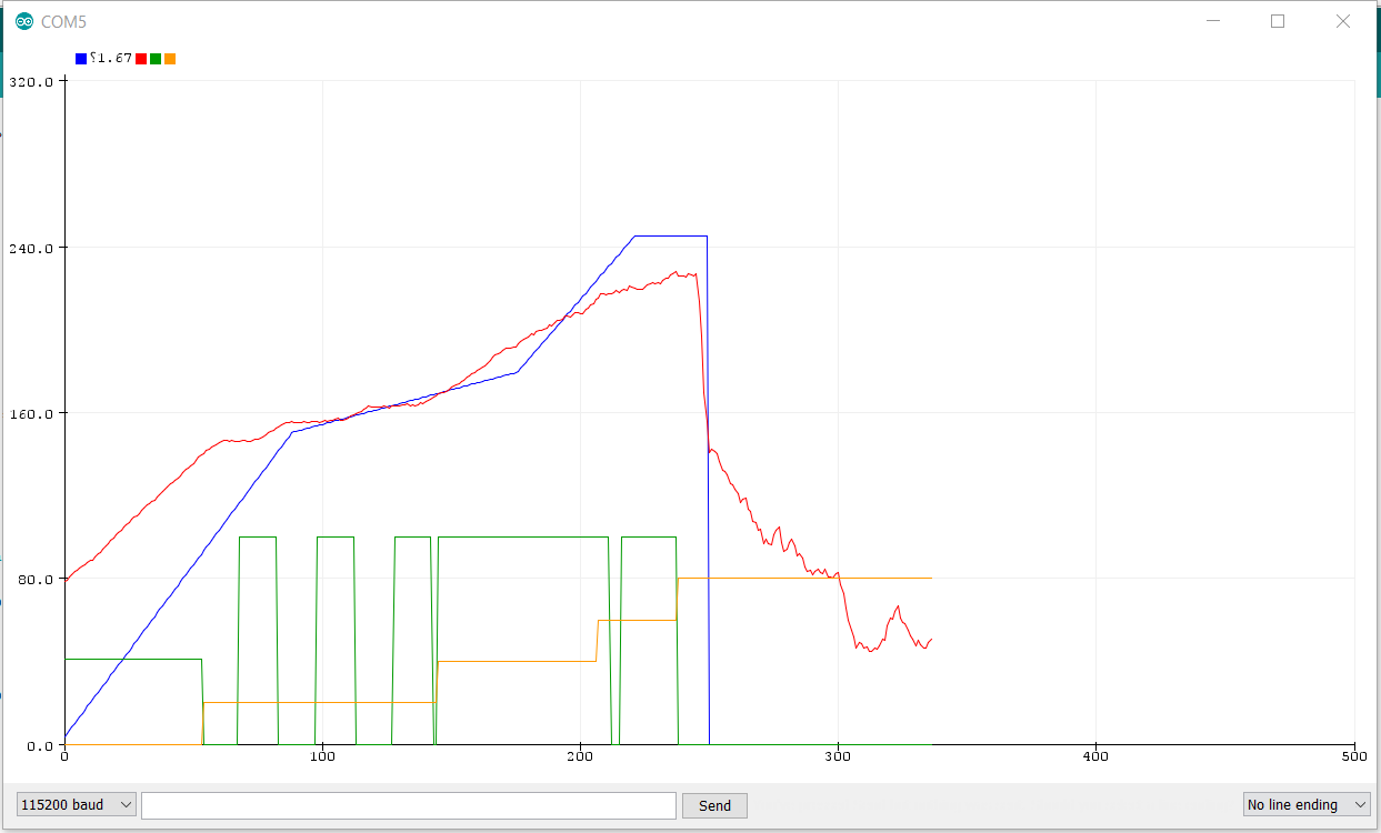
My last profile cooking actual panels and looking good!
The above screenshot is from my latest achieved profile using servo control. The different colored lines represent the following:
- Blue: Generic reference profile
- Red: Temp readings showing actual profile in the oven
- Yellow: Zones, stepping up through preheat, soak, ramp-up, reflow, cooldown
- Green: Servo position, represented by 0-100 percent power
Although this last profile screenshot is the result of almost 20 test runs and 10 actual board panels reflowing, I would like to mention that even with some slight variation between profiles, all of my panels came out beautifully. A good paste job and proper placement of parts can greatly help your initial yield, but I even had a few sloppy paste jobs and they came out fine!
Conclusion
 |
 |
| My complete setup in the garage. | Panel in the oven. |
If you're interested in reflowing some electronics using a toaster oven, it can be done using a simple Arduino, servo and thermocouple. It does take a little time to do some test runs and make slight adjustments to the provided Arduino sketch, but the results are pretty great! I currently have to watch the oven to manually open the door when it's done, but this could be automated. Plus, while one panel was in the oven, I simply started hand placing parts on the next panel and so no time was really lost.
If you would like to give this a try and have any questions, please reach out in the comment below or at the GitHub project repository.
Also, if you have any experience with solder reflow profiles, I'd love to hear your thoughts in the comments below.
Thanks for reading and cheers to some good DIY electronics SMD assembly!


Hi Pete!
Great project, and great writeup!
One comment that I'll make, though, is that those "ideal curves" aren't really as sacred as most people think. They are designed for "continuous" reflow ovens such as the one in SparkFun's production department, and these days for the parts designers to have a "target" for their parts designs to be able to survive.
I've had good success over the years using a flat electric griddle, a non-contact IR temperature guage to measure the temperature, and a couple of steel (NOT plastic -- they're too thick) spatulas (check places that sell "outdoor cooking" stuff for big ones!). The technique I use is to first use plastic stencil to put the solder paste on, a "bio-pick&place" machine (i.e., my hand, magnifying glass on a stand, and tweezers) to place all the parts, and then turn on the griddle (usually having it's temperature setting cranked up to max), and using the IR guage to watch the temperature. Once it's hot enough, carefully use the spatulas to transfer the board[s] onto the griddle (BTW, there will be "hot-spots", so beware if your board is too big, you may have to reposition or more times) and then watch for all blobs of paste to reflow, wait maybe 5 seconds, then again carefully use the spatulas to transfer the board to a heat resistant area (I usually use some scrap PCBs) to cool.
I've used this technique to do boards about 8" x 10" with around 100 parts, down to ones less than 1" x 1" with maybe 4 or 5 parts. The only problem is when you get things like 100 pin quad flat packs (e.g., some microprocessors) -- I've found that it's simpler to just leave them off during reflow, and solder them on by hand later, as they seem to almost always twist out of position.
One other related tip for the beginners: solder paste normally has a "shelf life" of about 6 months. If you seal it well (in a clearly marked container!) and store it in a fridge (just make SURE that nobody tries to eat it!) you can extend that to about two years. (BTW, don't freeze the stuff.)
Actually... I keep my paste in the freezer, and it lasts over 5 years. Just be sure to let it thaw before you try to squeeze it from the tube!
Dang. 5 years?! That's great! But I'm guessing that you may still want some fresher paste when it comes to finer pitch assemblies like 0402s, BGAs and stuff?
It seems to work okay still. Very few tombstones. I don't have the steady hands or eyes that I used to, so I try to not go below an 0603 if I can help it.
I don't buy stencils, so it's a somewhat arduous process of putting it on with a toothpick, and then using the toothpick to scrape some of the muck between the traces to reduce the number of solder bridges. It doesn't matter, though, I always manage to get a few.
I suppose I should put in an appropriate warning... DO NOT USE THIS TOOTHPICK FOR YOUR TEETH!
I have some here that is now somewhere between one and two years old. I don't go through it all that quickly. I've got little kids, so I don't keep it in the fridge or anywhere near food. I find that as it gets old it gets to be thicker and a little harder to work with. The parts don't stick to it so much anymore.
But I only do this with components on the top side, and am careful not to jostle them while transferring to the hot plate. Still melts and flows wonderfully and is super easy.
I sometimes use a toothpick, like you said, and sometimes I'll spring for a stencil. Just depends on the complexity of the board and what kind of timeframe I'm looking at. Doesn't cost too much to add a stencil to an order at JLCPCB, and a stencil from Oshstencils comes in the mail really quickly. This old paste has worked well for me both with and without the stencil.
If I was doing production work all day and the little bit of extra time mattered, then sure, getting fresh paste would make sense. For what I do, having it take an extra minute because it's a bit thick and not so sticky really doesn't matter at all.
Hi EJLANE,
Thanks for chiming in here. It is great to hear that most people are having good luck with the paste lasting so long. I hope that I keep enough projects going in my garage that I'll use this jar within 2 years - hopefully sooner, just need to keep on inventing :)
With your skillet method, do you manually attempt to create a soak zone before ramping up to reflow or just set to max and watch the paste?
I'm curious to know how necessary the soak is in a toaster oven setup. Maybe for designs with smaller parts that are less prone to be heat sinks, the soak may be unnecessary? Or could be shortened?
PS I, too, usually spring for the metal stencil from JLCPCB. It's seems crazy that they can offer a decent sized stencil for only 7 bucks more!
Exactly!
I do small batches of boards (maybe 5-10 about once a year or so. Some are fine pitch with some tough bits, but so far it's never been a huge issue.
I have 4 kids, but the youngest are 14, so no worries about the freezer. I keep the stuff in the very top (quick freeze area), and triple-bagged.
I reallty should add that you want to make sure that nobody tries to use that griddle for the morning pancakes or other food once you've used it for electronics!
Haha :) Indeed. It's funny that the article at X-toaster.com also has this warning in all caps and bold: " DO NOT COOK FOOD IN YOUR REFLOW OVEN! "
I bet, on about half of our tours at SparkFun someone always jokes about throwing a sandwich or a pizza through our big toaster oven (whoops, I mean reflow oven).
Hey #773!
Thanks for your kind words and great feedback.
Indeed, the skillet seems to be successful for a lot of people (including our very own founder, Nathan). Although it's pretty old now (2006), he wrote a great blog post here and shared his experience with skillet, toaster oven, industrial batch oven and hot air. He too, ultimately decided that the skillet was his favorite. We actually still have his skillet in the entry way at SparkFun. It's always a crowd-pleaser with the tours!
Thanks for the tip about the paste, I had no idea it could last that long! We fly through the stuff in production, and so never even come close to the expiration date. But I imagine this little 50g jar is gonna last me a long time with my garage reflowing.
"Bio-pick&place" :) I love it!
Sweet! I'm impressed by the use of the servo to control the temperature! =)
Thanks dude. Going into this, I was a little doubtful that a servo would work (so unlike me). I kind of thought I'd end up ripping it open and putting some SSR in there to have more direct control. But I was pleasantly surprised when I started seeing the plots. I swear, a standard hobby servo can solve pretty much anything!
Pete, You didn't specifically mention it is a convection oven, which helps to reduce temperature variations. I built mine with a PID temperature controller from Auber Instruments through eBay (about $75). There are now kits from China that include the PID, thermocouple, solid state relay, and relay heatsink, all for about $25 USD. As for solder paste shelf life, I store mine in the fridge, inside a sealed glass bottle, and turn the containers every six weeks to keep separation to a minimum. I have also used liquid flux to thin paste that has thickened in storage.
Hi #818, Thanks for commenting! I updated the post to highlight convection type.
I remember reading somewhere that the fan can potentially blow small parts off the board, but I haven't had an issue with this yet. I also have been taking pretty good care to push my parts into the paste just a bit. This is most likely helping them keep position.
What type/brand of solder flux do you use, and do you know of a good online source? I am lucky in that I can usually ask SparkFun production nicely and they will fill up my little jar from their massive jugs of the stuff, but I very rarely get into the office these days, and it'd be great to know for others without such sources.
Turning the paste containers every so often sounds like a good idea. Thanks for the tip!
I made my own & posted it in EE times long ago (2012). I like the way you simplified by using a servo to control the temperature knob - Clever!
I also find I have to open the door to get the cool down ramp. They have no active cooling, and no forced air from an external source - so whaddaya gonna do? ;)
IEEE Spectrum Article
Hi Tom, Thanks for sharing! Great article. Love the "poor man's solder reflow oven" title :) Are you still occasionally reflowing some SMD components at home with your toaster oven? I'd be curious to know how long mine might last, but then again, it would only be another 60 bucks to grab a new oven if/when this one bites the dust.
This has got me thinking... Do you know how long thermocouple probes typically last? I know it's a relatively cheap part to replace, but I wonder if there's any cleaning/storage techniques that could prolong its lifespan. I wonder which part of my setup will die first. Probably the heating elements or the control knob potentiometer. Maybe the servo?
PS congrats on getting published in Spectrum. Looks like you got a lot of buzz in the comments!
To answer your question about thermocouples - they last forever. So long as you don't bang them around. They're formed by a weld of two dissimilar metals. The only thing that will break them is severe shock/twisting, or if they corrode. And the high-temp inside the stainless tubes are, I believe, sealed.
Good to know. Thanks for that info.
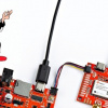
I currently have mine weaved through the rack a couple times and then it "floats" about 1 inche above and in front of the PCB. It enters the oven through a small crack in the door in the upper right. It's kind of hard to see in this pic, but if you zoom in, you can see the thin brown wire. The end is already kind of frayed, but I'm guessing that isn't an issue?
It doesn't really have to bend too much, so I'm' pretty sure it's really low stress on the thermocouple. I am thinking that next time I setup, I may move position to behind the PCB in the back, just to make swapping out panels a little less tedious. One time during testing I moved it forward closer to the glass, and it seems to indicate faster ramp ups. I'm guessing it might have just been positioned in a node of the moving air from the fan?
I'd maybe worry about the fraying - most people misunderstand how thermocouples work.. If the fraying gets through to the wiring, that coul be no bueno. Not dangerous, except that the temp reading could be wrong, and so things could go bonkers.
On mine, I drilled a hole through the oven wall and mounted it with the probe tip just under the wire rack. It never gets touched, and there's no issue with the door beating up any wiring. You might consider thiat simple mod to your setup.
I can't remember, is it a K-type you need for this temperature range (I think so) - take a look at something like this probe from Auber Instruments
Also - I've been considering adding a door kicker to mine ever since the second time I used it. If I run off to the bathroom or get otherwise distracted, it will burn the boards from letting them heat soak too long. The prepreg (or maybe glue) between layers softens up & the boards can "potato-chip"
The faster ramp-ups might imply it's just closer to one of the quartz elements. That's what I like about the above probe - it's always in the same spot, and so your oven configuration never changes. That's one of the most important parts of any process - making sure configuration doesn't change! As soon as it does, all your calibrations might just go right out the window. Fortunately, the solder curve has a lot of margin
A mounted probe tip sounds like a good idea. That will most likely be my next upgrade. I think I'll give it a try with the stainless steel one we offer here:
Thermocouple Type-K - Stainless Steel
Thanks again for all your advice! I'd be interested to hear about how you solve the door kicker. Please report back if/when you come up with something. Cheers!
I don't see it happening in the near future, but now that you've given me a push, maybe it'll happen ;)
The original (not safe for a publication) writeup of the oven - a little more inf on there on the particulars...
My oven is still going. I don't use it real often - it goes in batches. Every year or two I'll have a project that ends up running multiple batches through as I troubleshoot, etc. I think the last project was middle of last year. It was something I call a "pi plate" - 4 pi zero Ws on a single carrier card with IO broken out, some status LEDs, and a couple lines of communication between them...
Regarding the use of a skillet, I've read somewhere that putting a layer of sand in the skillet will even out the heat to avoid hot spots.
Have been considering a similar project but was planning on using a pure copper plate with thermocouple( s ?) attached in the fry pan. Thoughts ?