
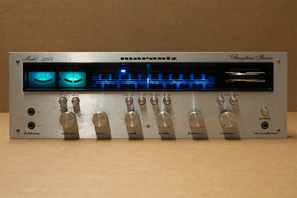
The centerpiece of my living room is my old Marantz 2245 stereo receiver. It's heavy, but it sounds good---and looks good, too. It's got a retro-futuristic silver aluminum faceplate, the fancy script "Stereophonic Receiver" logo, the aluminum control knobs, and icy blue panel illumination.
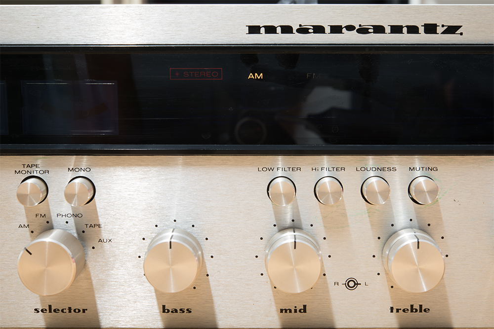
The lonely AM indicator light.
Really futuristic---but that future was growing increasingly dark. The control panel is filled with incandescent lights to illuminate the back of the meters and tuning scale, and indicate the active input. Over the years, those lights went out, one by one. The only light still functional was the AM indicator; it was probably still there because I don't really listen to AM, so it's lived a gentle life.
For ages, there's been a flashlight sitting next to it, so I could peer in and tune the receiver.
The time had come. It needed new lights.
Before I started, I had a handful of goals. I wanted to:
- Get the lights working.
- In such a way that I didn't have to go in again too quickly and redo the fix.
- And not do any further damage.
The Guts
So I dove in and assessed the situation.
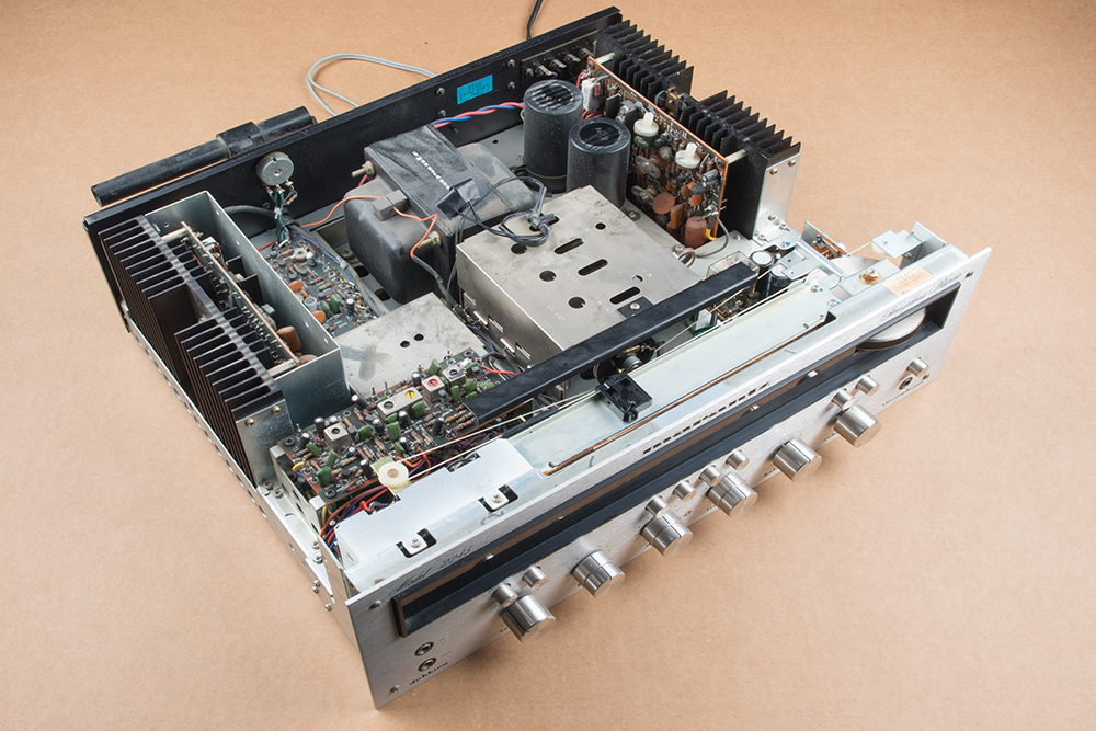
We really don't make electronics like this anymore. There are a dozen circuit boards, each populated with discrete transistors. The chassis is assembled from approximately 30 separate pieces of flanged, drilled and tapped sheet metal.
The bulbs live behind the front panel. The dial lights are in a trough behind the dial, and each mode lamp has its own little cubbyhole, so it won't illuminate its neighbors. There's also a little trapdoor behind the signal strength and FM tuning meters, with two more bulbs.
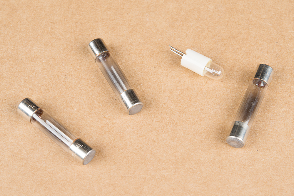
Old, dead bulbs.
There are two different types of incandescent bulbs inside. The first are in little glass tubes the size of AG3-size fuses. The others are 5mm grain-of-wheat bulbs, of historical interest because the 5mm size (also known as T 1-3/4) was copied by LEDs.
As I was getting deeper into the guts, I was also doing web research. The service manual is available from Audiokarma. It's from the golden age of service manuals, 33 pages long, with a detailed theory-of-operations, calibration and troublechooting procedures, and parts schedule. Page 25 is the complete schematic, a single A3 page. Analyzing the circuit more carefully showed the incandescent bulbs hung on their own secondary of the power transformer. No rectifier or regulator in line---these bulbs are getting 12 volts Alternating Current!
That secondary is a pair of green wires, like the heater secondary on a tube amplifier. They snake their way through the chassis and emerge to run straight to the bulbs behind the tuner scale, then daisy chain to the other bulbs.
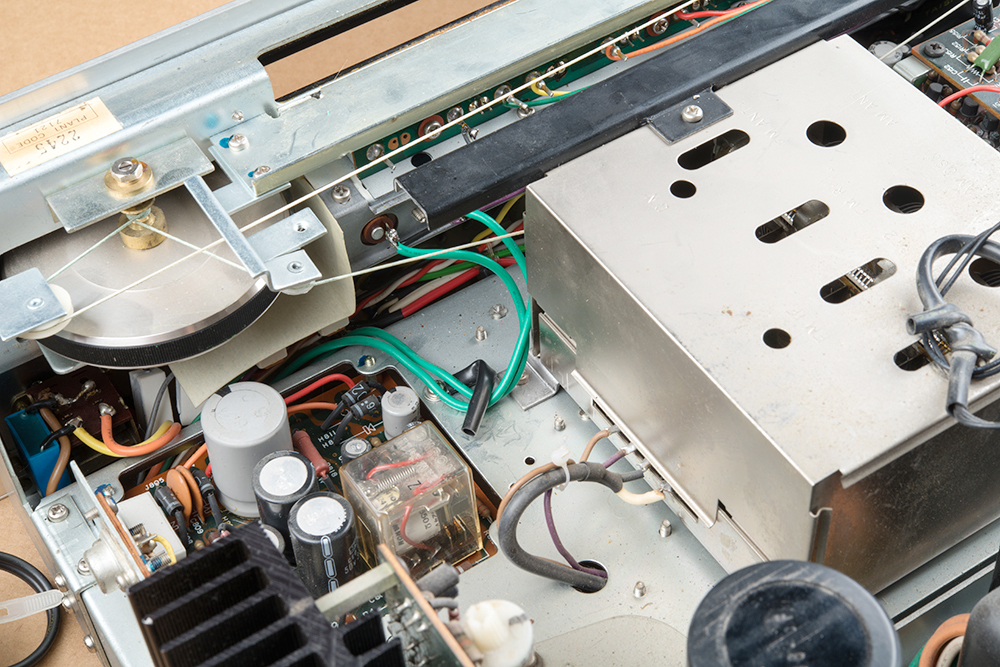
Green wires for the "filament" supply.
I also looked at some websites, watched some videos, and did some component research. The original bulbs are still available, and not expensive, but they don't meet my second criteria.
In researching replacement bulbs, I found an LED replacement for the fuse bulbs from Parts Express and ordered 10 pieces. They have three white LEDs on a little PCB, with caps on the ends to fit in the fuse holders.
I didn't find a suitable replacement for the 5mm bulbs. Again, the size would indicate that a 5mm LED is about right.
But it's never quite that easy.
To simply drop an LED and bias resistor in for each LED wasn't looking like a good option, again in light of criteria #2. Checking specs for white LEDs, they typically have a maximum reverse voltage that's not much higher than the forward voltage, and simply hanging between the 12 VAC lines meant they'd be reverse biased half the time. One datasheet stated a maximum 5V reverse voltage; another said "device is not designed for reverse operation." Exceeding the manufacturer's recommendations is a path to early failure.
A little more careful analysis of the circuit showed that this transformer secondary is used exclusively for the bulbs. So I added a full-wave rectifier and filter cap, turning AC into DC, eliminating the reverse voltage problem without causing problems elsewhere in the unit. The DC bias also keeps the LEDs from flickering.
Replacement Parts
Having come to the conclusion that reverse bias is a bad idea on white LEDs, I had some concerns about how the replacement fuse bulbs handled the 12 VAC. Before installing them, I did a quick bench test. It turns out they illuminate when they're biased in either direction! There's a little more to the circuit than I was anticipating---I could see there was something under the end caps, so I removed them for a closer look. There are some SOT-23 diodes that form a full-wave diode bridge. The LEDs sit in the center of the bridge, always forward biased, regardless of the polarity of the applied voltage. Clever!
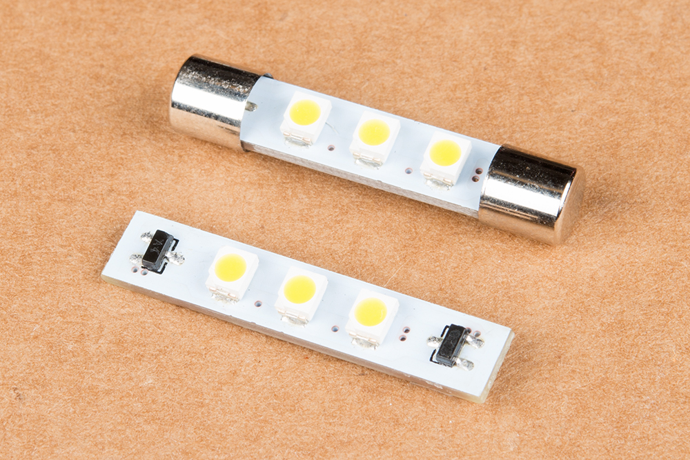
Replacement AG3 LED Module.
The original fuse bulbs were rated at 200 mA each, and there were seven of them, for a total of 1.4 A. The replacements draw about 40 mA, one-fifth of the original load.
For the grain-of-wheat bulbs, I fashioned replacement assemblies with a 5mm white LED and a 1K Ω resistor, with the leads insulated with heat-shrink tubing. After some experimenting, I found that I needed to roughen the surface of the LEDs with sandpaper, to diffuse the beam a bit.
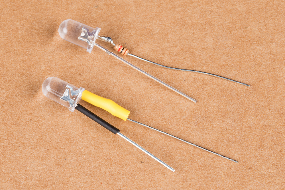
5mm bulb substitute.
Again, the current draw of the LED replacements is significantly lower than the originals---about 10 mA versus the original 40.
Rectifier Board
To get my DC, I built a full-wave rectifier with four 1N4004 diodes on a mini solderable breadboard, with a 1.1 Ω series resistor and a 1,000 uF electrolytic filter cap.

Rectifier board in place.
The board was mounted on an angle bracket, attached to the chassis using the screw that originally held the retainer clip for the green wires.
Careful Surgery
If you look at the pictures above, you'll notice that the tuning mechanism uses a set of pulleys and string to link the tuning control, the indicator needle, and the wheel on the front of the receiver module. The 5mm bulbs are beneath the middle of that loop of string. Everything I read indicated that it's a serious hassle to have to replace that string, so in keeping with principle #3, respecting the string was a high priority. But I also had to desolder the 5mm bulbs from the PCB almost immediately under the string.

I wound up suspending the string behind the aluminum rail with cross-lock tweezers, leaving clearance for me to reach in with a soldering iron. Desoldering was easier than anticipated, because the lead solder has a lower melting temperature than lead-free. I pulled the 5mm bulbs from the front with small pliers, while heating the solder from the back, then cleaned up the excess solder with some wick.
I had to be a little extra diligent installing the replacement 5mm assemblies, as they are polarized, and they don't all face the same direction.
The fuse bulbs sit in standard fuse holders. They simply pop in and out, not requiring significant force or desoldering, and, as mentioned above, they're not polarized.
Results
I worked carefully, incrementally testing as I went. I think the results speak for themselves.
So how did I do at achieving my initial goals?
- The lights are working! #1 is a success!
- But for how long? In general, LEDs have longer life cycles than incandescent bulbs, but the ultimate longevity remains to be seen. I'm hoping they outlive me.
- And doing no further damage? Let's just say I didn't hurt anything else that I couldn't fix. But those yaks are a tale for another time.


Work of beauty. It would be a really fun job to offer this service just to see the old equipment that came through; I just couldn't convince my wife to make a hobby of it.
Man I miss my youth. I was a self taught hobbiest, studied electrical engineer in college and graduate school but when most of the research labs in New Jersey closed, I switched to IT. I haven't built a circuit in 20 years and I regret it. My skills are so stale.
Reading this post brought back a lot of fond memories. Any suggestions on getting back into this?
Also it depends what you want to do. Are you looking to play with analog receivers or are you looking to play with microcontrollers. Like Byron said, we have a bunch of kits geared towards helping you get started with Arduino, Intel Edison, Raspberry Pi, etc that are a good place to start to learn about some of the newer and popular technologies.
Some ideas, in no particular order:
Really, it comes back to where your own interests and aptitudes lie!
I had a similar background. Got Ham License at 14, went to engineering school. Worked for Bell Labs for many years. I still like to build stuff. If you are still in NJ, there are three makerspaces that can help you. IXR in Wall Township, Fubar Labs in New Brunswich and MakeBar in Hoboken. I am a member/host of IXR and get my electronics fix by attending meetings. Joe W.
I have a 2270 I re-lamped a few years back. Sadly, the effort did not meet your criteria #2! I will use the info here (great find on the fuse LED bulb!) the next time I go into it. Thanks for posting the research info. I was thinking of using LEDs, but I never motivated myself to do it. My unit has the same stereo mode lamp circuit, so I appreciate the comment on that as well.
You did not mention color in your list, did you give any thought to a red/green LED? No rectification necessary and it glows a nice warm yellow/orange.
It might have been a good time to check the aged electrolytic capacitors in the Marantz. They can lose capacity over time, compromising peak power, distortion and line-hum suppression.
I thought the same thing. Even though older electrolytics were not made as poorly as many are today, even the best older ones aged as their seals were not 100% perfect (what is?). That's my biggest fear about turning on my 30 year old, 400 Watt Kenwood tuner/amp that's been "silent" for about 20 years! It may be a boat anchor at close to 40 pounds in weight (transformers are heavy), but it had really sweet lows and was quiet as a mouse (no rumble/hum/hiss).
Just added that to my bucket list along with dusting off my LP collection and getting my old Panasonic Direct Drive phonograph running too.
In the mid-70's, an audio seminar by the late Dr. Richard Greiner compared the schematics of the Phase-Linear 400 Watt amplifier to the competing Marantz 400 watt. The P-L amp was a straight-forward class A-B differential design on one page. The Marantz went on for several more pages of circuitry, much of which was devoted to Inter-Modulation-Distortion suppression. That kind of distortion introduces frequencies which are not harmonics of the source signal, and so are particularly aggravating. The audiophiles must have dominated the bean counters at Marantz in that era.
Your repair looks good! One thing I hope doesn't bite you, the DC voltage now available on the lamp power rails will be a bit higher than the RMS AC voltage was because of the filter caps charging up to the PP voltage. While you will get a 1.2 volt drop across the bridge rectifier, that will be more than made up for by the lower voltage drop in the transformer windings due to the lower current of the LED bulbs. Bottom line is that those 'fuse' based bulbs could see a bit more voltage than they were designed for depending on the design voltage output of that transformer winding. At least those are easy to replace. As for the soldered in LED's, I found that it's a bad idea to run LED's anywhere near their max rated current, especially if they came from China. My experience with that was a VERY short life time as the LED's got dim within a few weeks of operation (this was in an outdoor lighting application where the LED's ran about 6-8 hours a night, every night). Cutting the current in half made a huge difference in the aging rate of the LED's. I hope you sized the series resistors accordingly.
Great write up on a beautiful piece of gear!
Another way to deal with the reverse bias problem for the 5mm LEDs would be simply to put a small diode across the LED pins to short the reverse current. The bias resistor to set the forward current would also limit the reverse current to an acceptable value. No rectifier board needed.
Another way to skin this cat would be to put a small diode in series with the LED to be able to use the reverse breakdown of the diode instead of the LED. But I think we are probably getting a bit clunky with all the components behind each 5mm LED. His actual solution by using a bridge works well (and allows using his use of a cap to reduce the flickering as was discussed in another comment thread).
Nice story. I like seeing care taken to work with electronics that we no longer build. Thank you!
Yup, got the same unit in my living room as well. And the lights are all gone too. Been thinking about doing this for years...
Really nice job. Good stuff!