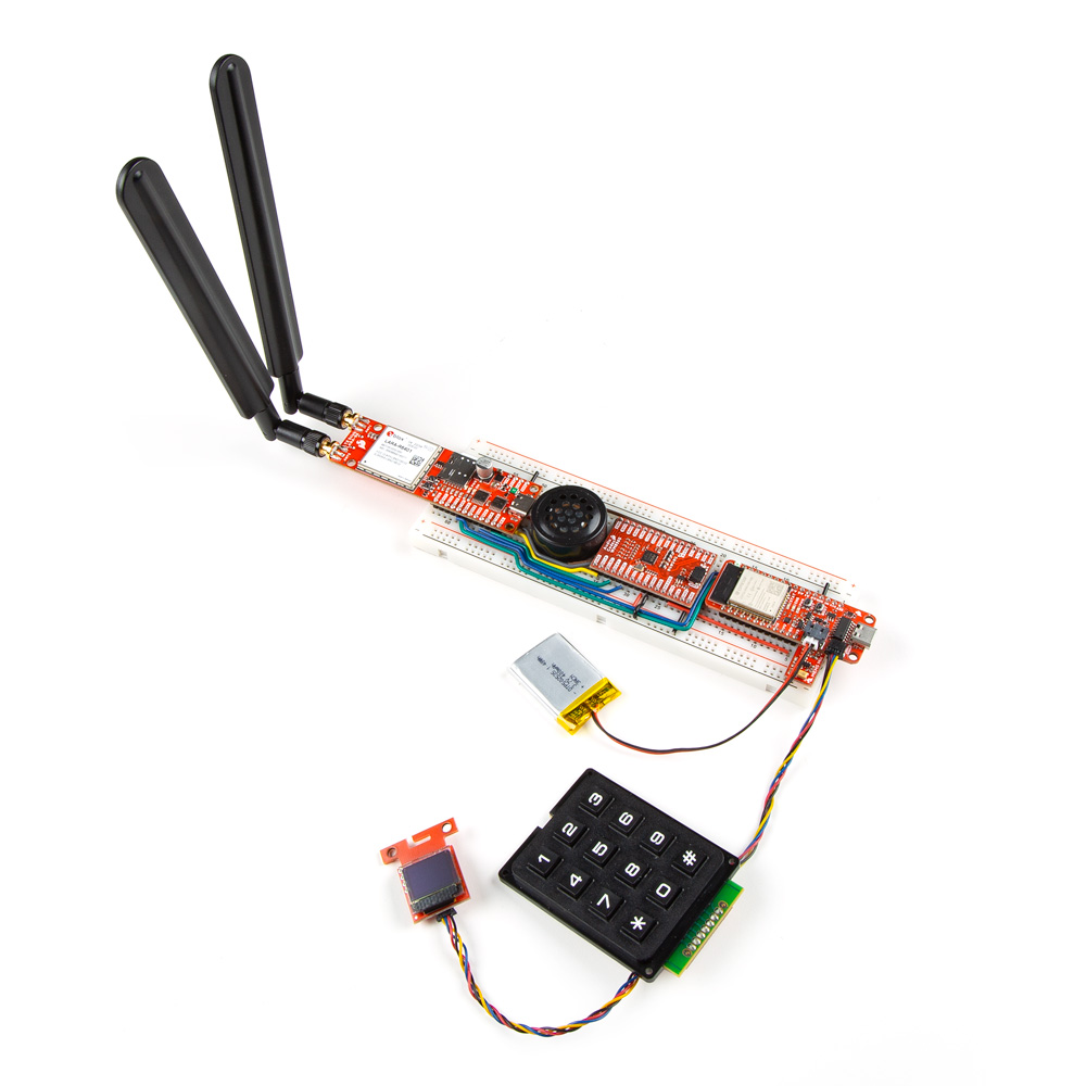
Build Your Own Breadboard Phone!
Have you ever wanted to build your own phone from scratch? Preferably on the most ubiquitous electronics prototyping platform for maximum flexibility and minimum ergonomics? Now you can!

In our recent product showcase video covering the new SparkFun LTE Stick - LARA-R6, I showed off a project of mine that uses the LTE Stick in a fun way; I call it the Breadboard Phone!
For anyone who hasn't seen the video, jump to 8 minutes into the video to see it in action!
In this post, I'll walk you through how to build a Breadboard Phone of your own! Though a quick head up before we dive in - this is by no means a complete project! This was really just intended to be a fun demo of the LTE Stick, so not everything has been thought through completely, and the software has some rough edges and missing features. So you'll need to do some work if you really want this to function well.
Required Materials
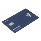
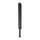
First and foremost, you'll need an LTE Stick! That was the original motivation for this project, right? Don't forget to get a couple LTE antennas too! And you'll need a SIM card to connect to a network with a plan that includes the features you want; finding a suitable SIM card is arguably the most difficult step. For instance, the Hologram SIM card we sell is really only intended for data; sending texts can be hit or miss, and it doesn't support phone calls. We bough a Cricket SIM card that worked fine in my phone, but they suspended service after inserting it into the LTE Stick with a text message saying it's an "unsupported device" despite the fact that it worked fine for the 2 minutes before they stopped the service... I ended up using my personal SIM card (carrier is Ting) and that worked totally fine.
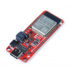
Second, you'll need a microcontroller to handle all the main logic of interfacing with the user inputs/outputs and telling the LTE Stick what to do. You don't really need anything special or fancy for this, I just chose the ESP32 Thing Plus because I had one lying around on my desk. However because its fairly powerful and has built-in WiFi and Bluetooth, that leaves lots of room for expansion with this project!
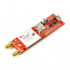
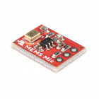
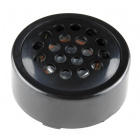
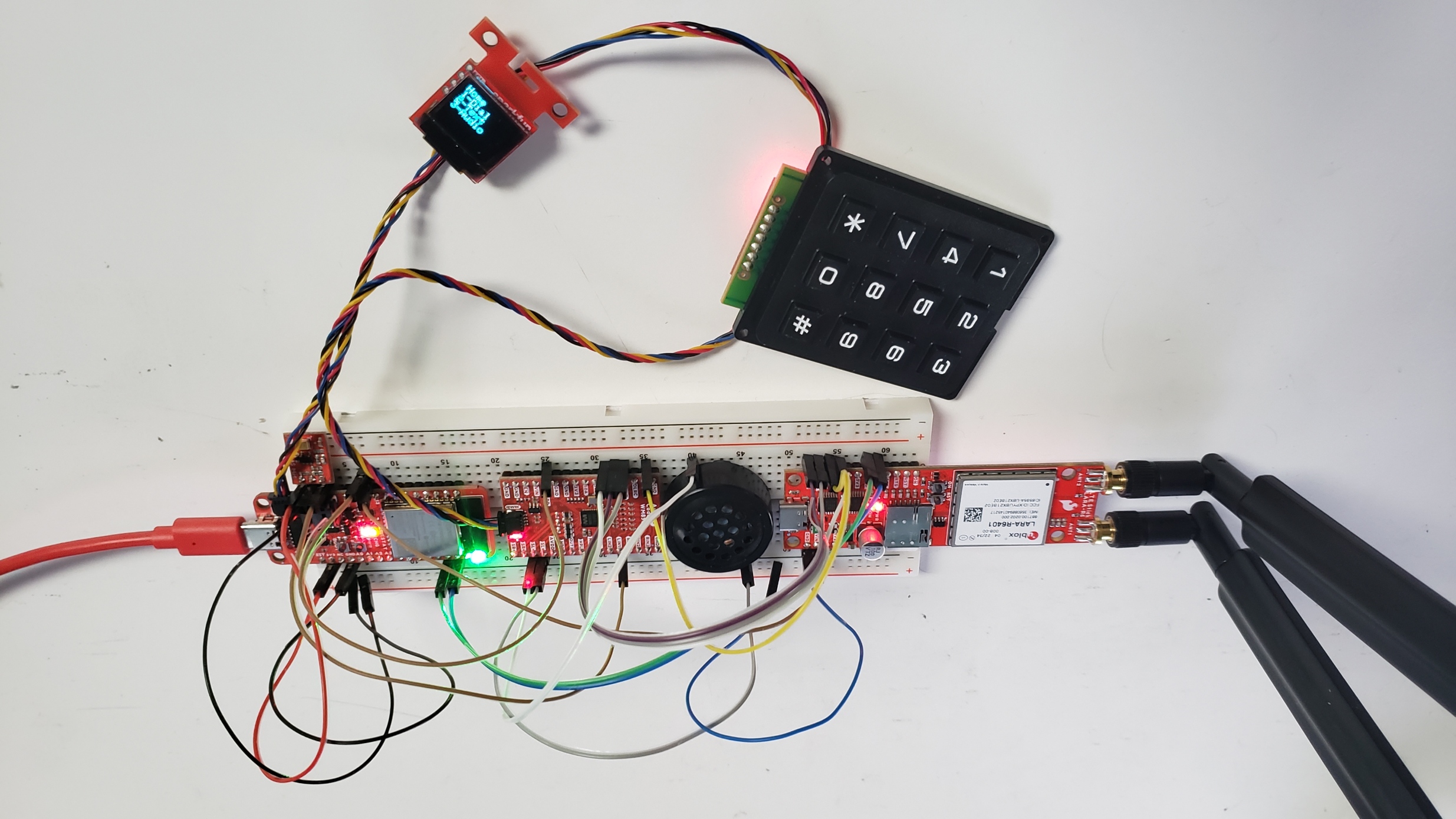
Next, you'll need a way to input and output audio. The LTE Stick has I2S audio pins broken out to PTH headers specifically for this purpose, and is intended to connect to an audio codec. For this, I used the WM8960 audio codec that Pete made about a year ago, and it works great for this application! In addition, you'll need a microphone and a speaker to actually measure and create sound waves. I used the SPH8878LR5H-1 MEMS Microphone for its small form factor that can sit right next to the Thing Plus at the end of the breadboard, and this PCB mount speaker which just barely squeezes into the space remaining on the breadboard.
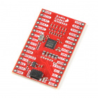
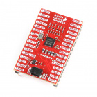
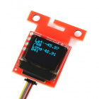
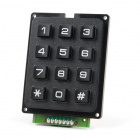
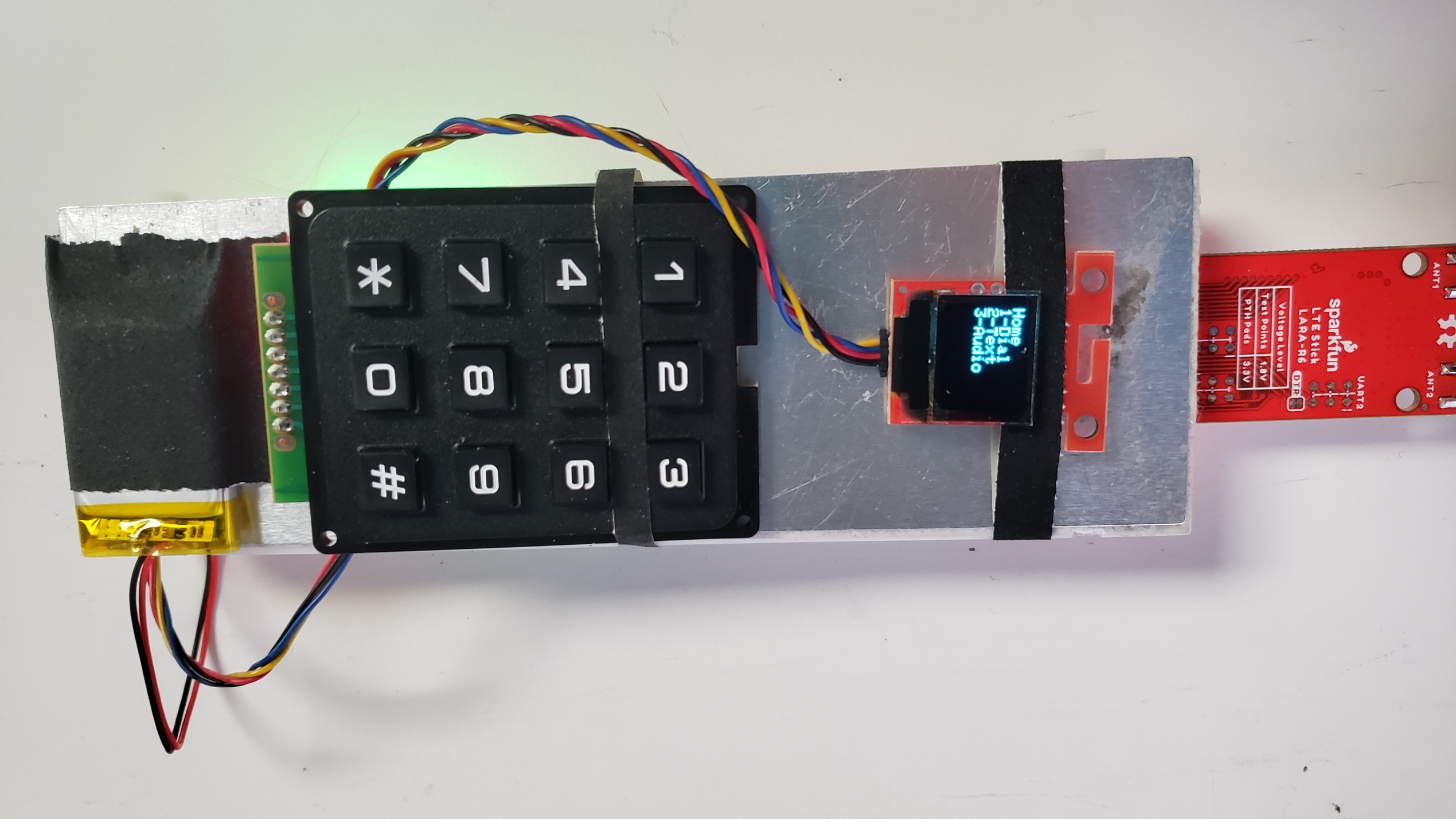
You'll need a couple components for user input and output. Of course, I used the Qwiic Keypad for user input - how could you not use that for a phone project! And for displaying stuff to the user, I used our Qwiic Micro OLED. In hindsight, this was probably not the best decision, the screen is really too small for this project. I just grabbed it early on while prototyping, and the project grew with it, so it became too much effort for me to bother refactoring what was needed to use a bigger display. If you're using Qwiic components, don't forget some Qwiic cables!
Oh, and if you want to battery power this project, you'll need a LiPo battery as well! I wasn't too worried about operating duration, so I arbitrarily picked this 400mAh battery, but you can always go bigger if you want it to run for longer!


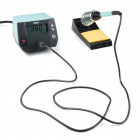
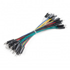
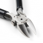
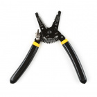
Lastly, you'll need components to put everything together. You could obviously do this however you like, but as someone who is a bit too passionate about breadboards, I of course had to stick everything into a breadboard. If you choose to go down that route, you'll also need wires to connect everything. You could use normal breadboard jumper wires, but 22AWG solid core hookup wire is really recommended here; you'll also need tools to cut and strip the wires. And some soldering will be required to attach headers to the boards, so you'll need an iron and solder.


And here's all those parts in a single wish list in case you want to add them all to cart with a single click!
Assembly Guide
Right, let's dive into the assembly! Like mentioned above, you can use normal breadboard jumpers if you wish, and that's what I did to begin with! However this project requires a lot of wires, so it gets messy pretty quickly, and full size jumper prevent you from being able to hold the phone next to your head properly. This is the mess I was dealing with!
So I definitely recommend making custom jumper wires that are the exact length needed for each segment. This is something I picked up from Ben Eater, who makes fantastic computer engineering videos on YouTube! This video of his gives an excellent explanation of the technique. The TLDW is to use 22AWG solid core wire, and bend it into the shape you need with an extra 0.3" at each end to strip the insulation from to insert into the breadboard rails.
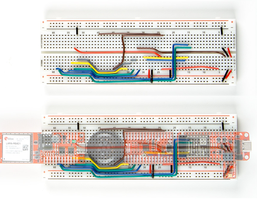
Below is a closeup of the breadboard I used with all the components removed so you can see exactly where each wire goes. Below that, we've also overlayed the components so you can see exactly what pin each wire is meant to connecto to. Note that some wires go under components in order to make it look a bit neater.
Something else to note - you'll need to choose how to power some components. I used the 3.3V pin coming from the Thing Plus board to power the microphone and digital IO pin of the audio codec, but the speaker and LTE Stick require a bit more voltage/power than the 3.3V pin can supply. Because I want this project to be portable, I used the VBAT pin on the Thing Plus, which connects directly to the LiPo battery. The restriction here is that you must have a battery plugged in for the LTE stick to actually turn on properly. An alternative solution is to use the VUSB pin, which connects directly to the USB connector on the Thing Plus; the downside here is that it won't be portable.
Once the breadboard is all wired up, the last step of the assembly is to insert your SIM card, connect the keypad and display with a couple Qwiic cables, and connect the battery. Unfortunately there's really no more room on the breadboard for these to go, so I just taped them onto the back of the breadboard.
It's not the most elegant solution, I know; I just ran out of time to do something better. One fun suggestion I heard was to add those parts onto a second breadboard, then connect both breadboards with a hinge to create a Breadboard Flip Phone! I love the idea, but it's unfortunately beyond what I have time for now.
And that's all for the hardware assembly! If you decide to recreate this project, I'd love to hear if you improved on this!
Software
The last major step is to flash the code onto the microcontroller. All the code I wrote is written in Arduino and stored in the GitHub repo for the LTE Stick, so you can just download it and flash it onto your board. It does depend on our new u-blox Cellular Arduino Library, so you'll need to add that before you can compile and upload the code.
Some features are also specific to the ESP32 Thing Plus, so if you're using a different development board, you may need to make some changes there. And as I mentioned at the start of this post, this project was originally only intended to be a demo of a fun way to use the LTE Stick rather than a final project, so the code is by no means perfect. I haven't implemented a whole lot of features, it's not at all optimized, and it doesn't handle all the edge cases. It's really just a proof-of-concept to demonstrate the project and it's not ready for prime time, so you'll probably want to add some code of your own to get it working better.
Usage
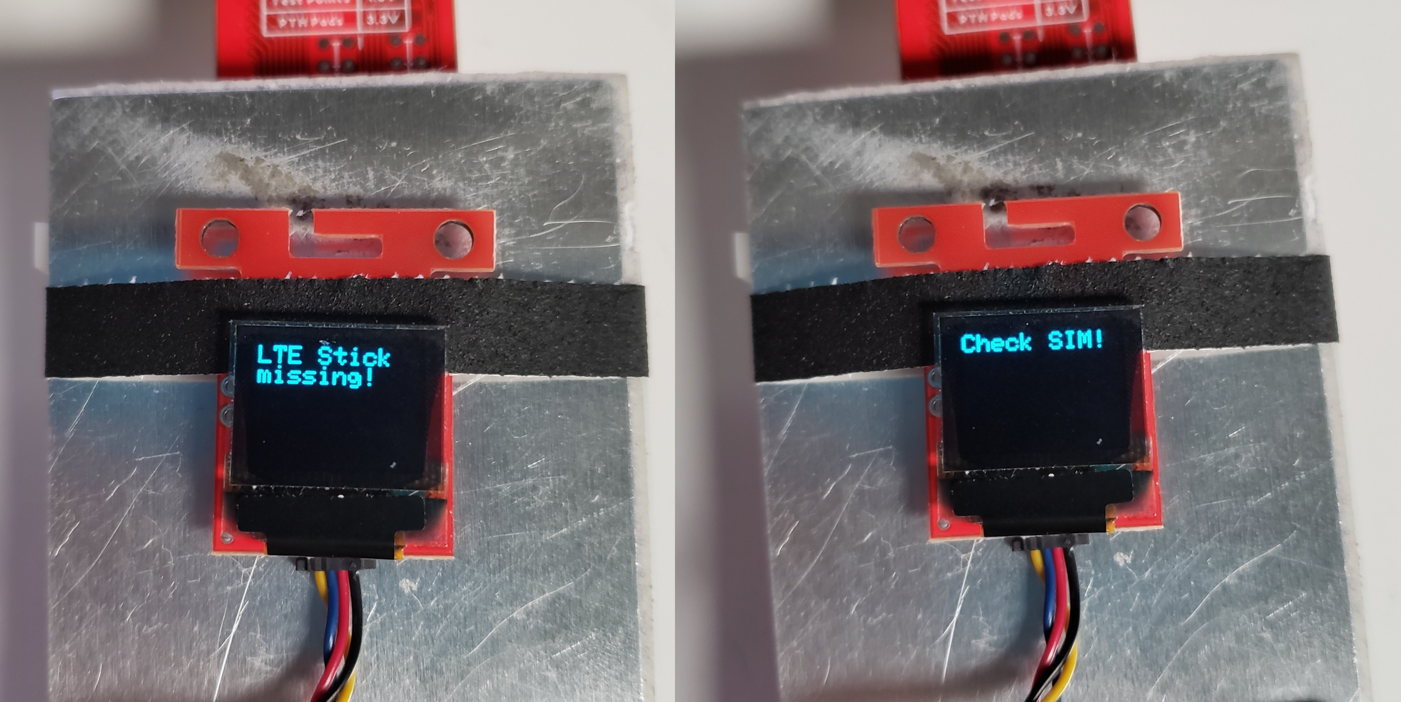
And that's it! Power it up, make sure to press the ON button on the LTE Stick, and the code will check that everything is connected. During this time, it will use the OLED display and the RGB LED on the Thing Plus to give status information, as well as printing debug messages over Serial in case you need that. Here's what it shows during startup:
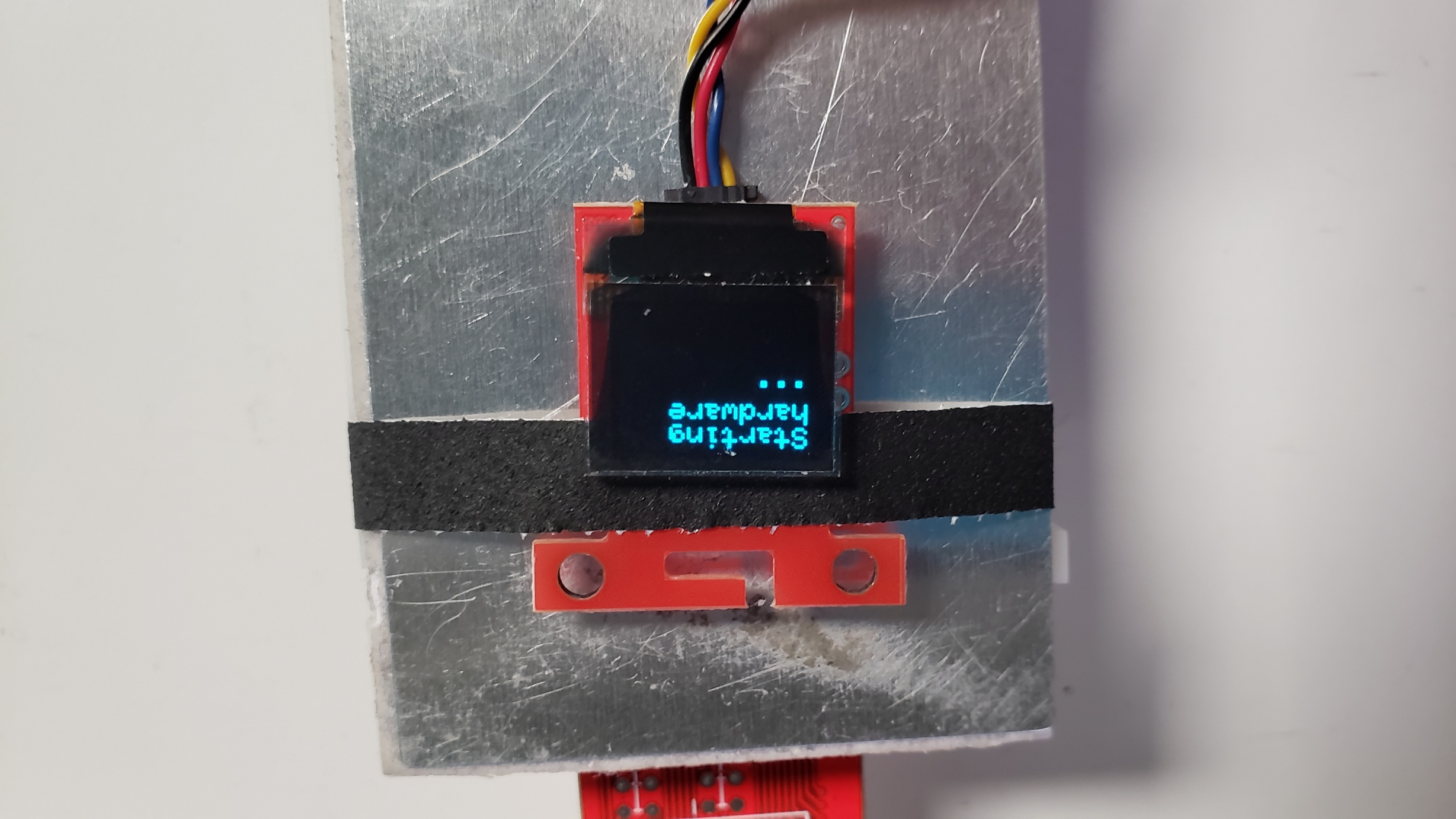
The RGB LED will be blue during start up, and change to green if successful, or red if there's an issue detected. If the OLED is working, a message will be displayed on it indicating the exact problem. For example, if you forget to press the ON button on the LTE Stick or forget the SIM card, it will display one of these messages on the OLED:
If you're running into trouble, double check the wiring and try running some of the examples from the SparkFun u-blox Cellular Arduino Library. Assuming all goes well, the main menu will be displayed on the OLED.
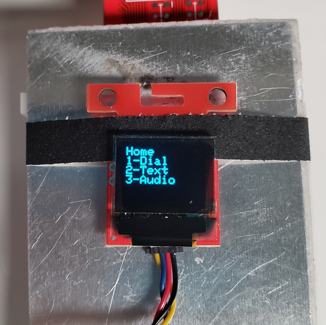
From there, you can used the keypad to navigate around and do stuff! In general, the numbers are for user input and selecting sub-menus indicated on the display, the * button will delete input or go back through menus, and the # button is used to finish entering inputs.
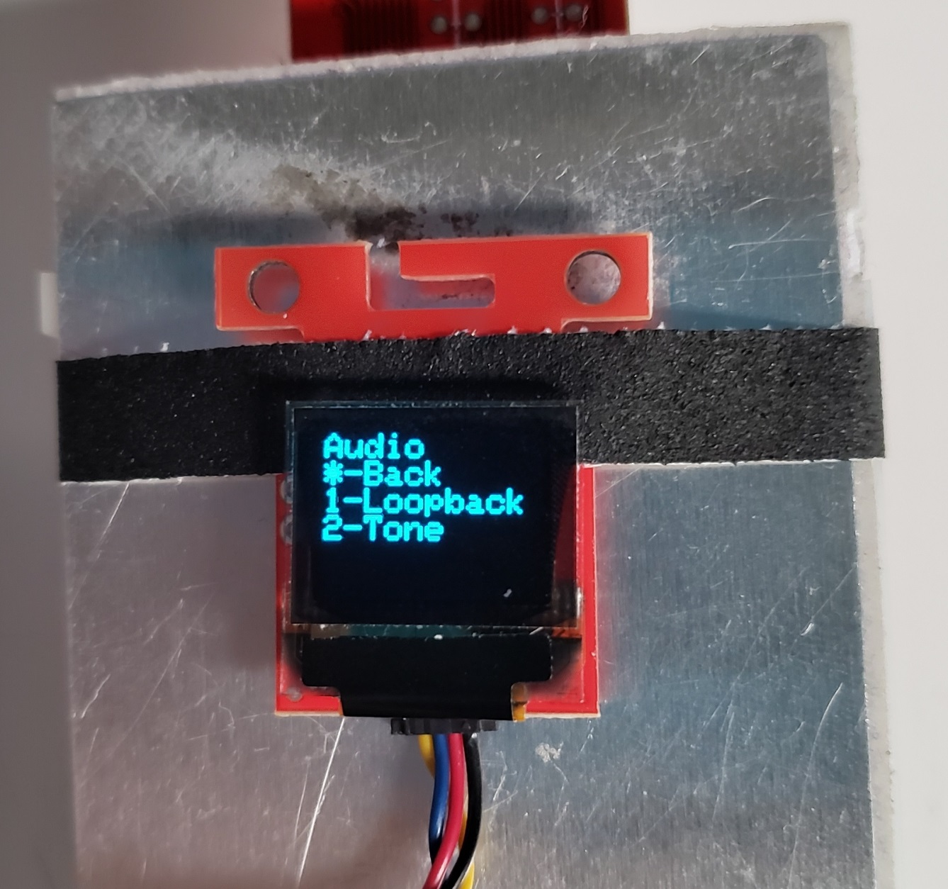
Before diving in though, I'd recommend doing a couple things to verify everything is working. First, the code is setup to generate a short tone through the speaker whenever a key is pressed on the keypad. Press any of the keypad buttons, and the speaker should play a DTMF tone corresponding to whatever key was pressed. If you don't hear it, you should troubleshoot that before moving forward. Check the wires are all going to the right spots, and try running the Arduino examples for the audio codec.
Assuming that works, enter the audio menu and run the loopback test to confirm whether the microphone is working too. Be warned, this takes the microphone output and sends it straight to the speaker, so it will create a lot of feedback and can get very loud very quickly! Pressing the * button should stop it, but you could also cover the speaker with your hand or be ready to unplug something if needed. Again, if this does not work, you should troubleshoot it before moving forward.
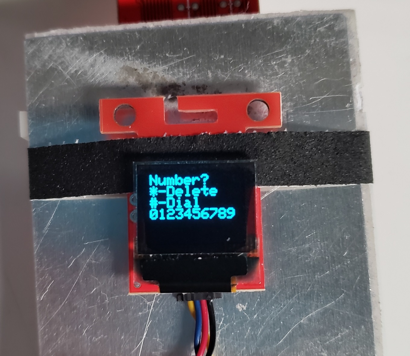
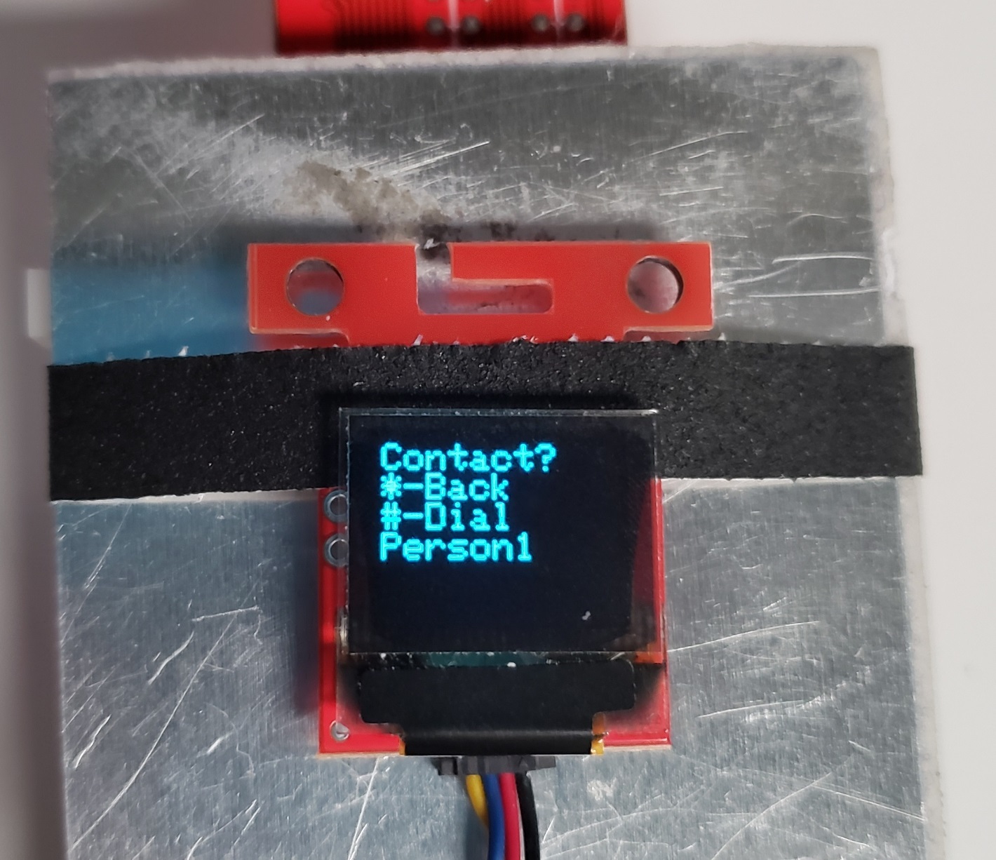
If the loopback test works, then that means pretty much all of the hardware is working correctly! The last test is to see if you can make phone calls. From the main menu, enter the dial menu, then enter the number you want to call. Once finished, press the # button to dial the number. Assuming all goes well, the other phone should ring and you should be able to have a conversation with the other person! And you can press the * button to end the call.
If you have any trouble making the call, be sure to try the audio tests described above, and try some of the networking examples from the SparkFun u-blox Cellular Arduino Library. Also make sure that your SIM card works with the LARA-R6, and that your data plan support phone calls.
In addition to phone calls, you can send text messages! Enter the text menu, then enter the message you want to send. For those familiar with old flip phones, I've implemented a primitive version of T-9 typing! For those unfamiliar, you press the same button multiple times to cycle through 3 or 4 different characters (1 is used for punctuation, 2 is used for ABC, 3 is used for DEF, etc.). Press the * button to delete a character, or the # button to finish.
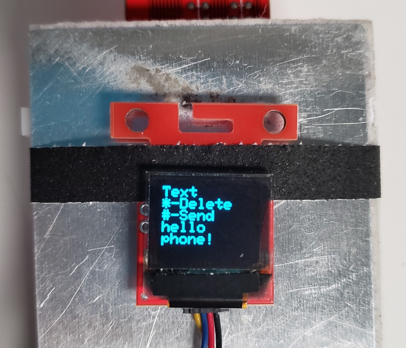
Once done, you can then enter the number to send the text to, then press the # button again to send the text. If you get tired of entering people's phone numbers all the time, you can add them to your speed dial contact list! I've implemented this as part of the Arduino code, so you'll need to edit that for this feature. Open the Breadboard_Phone_Definitions.h file, and near the top is where you can set your contact names and numbers. Once done, re-upload the code and any time you're in the dial menu, press the # key to enter the speed dial menu; each key will correspond to your contact list.
The last major feature is that you can also receive phone calls, but that's about the extent of what I implemented. Like I said, there's definitely a number of features absent, such as receiving text messages. If you choose to do this project yourself, I'd love to hear how it goes for you and whether you expand on my existing implementation!


