Correction data is used in surveying and navigation to enhance the accuracy of Global Navigation Satellite Systems (GNSS). These systems, such as the GPS, provide positioning information by receiving signals from multiple satellites. However, various factors can introduce errors into the measurements, such as atmospheric delays, satellite orbit inaccuracies, and receiver clock errors.
GNSS can provide accurate and reliable positioning information anywhere on Earth. GNSS enables precise determination of latitude, longitude, and altitude by leveraging a constellation of satellites, allowing users to navigate with confidence. It plays a critical role in various sectors, including transportation, emergency services, surveying, and agriculture, where it enhances efficiency, safety, and effectiveness in navigating the increasingly interconnected world. It's also crucial for scientific research, geodesy, and monitoring of tectonic movements.
Correction data provides precise information about errors and enables users to mitigate them effectively. By applying correction data, either through ground-based reference stations or satellite-based systems, GNSS receivers can significantly improve their positioning accuracy, especially in real-time applications where high precision is crucial.
Signal Errors
The GNSS works by utilizing a constellation of satellites that continuously transmit signals containing information about their locations and the time the signals were transmitted. Receivers on the ground or in vehicles receive these signals and use the timing and location information to calculate their own positions through a process called trilateration.
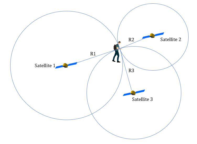
Trilateration involves measuring the time it takes for the signals from multiple satellites to reach the receiver. By knowing the speed of light, the receiver can calculate the distance to each satellite based on the time delay. Using GPS, you need to know the distance to three satellites to pinpoint a location, and a fourth to account for clock errors.
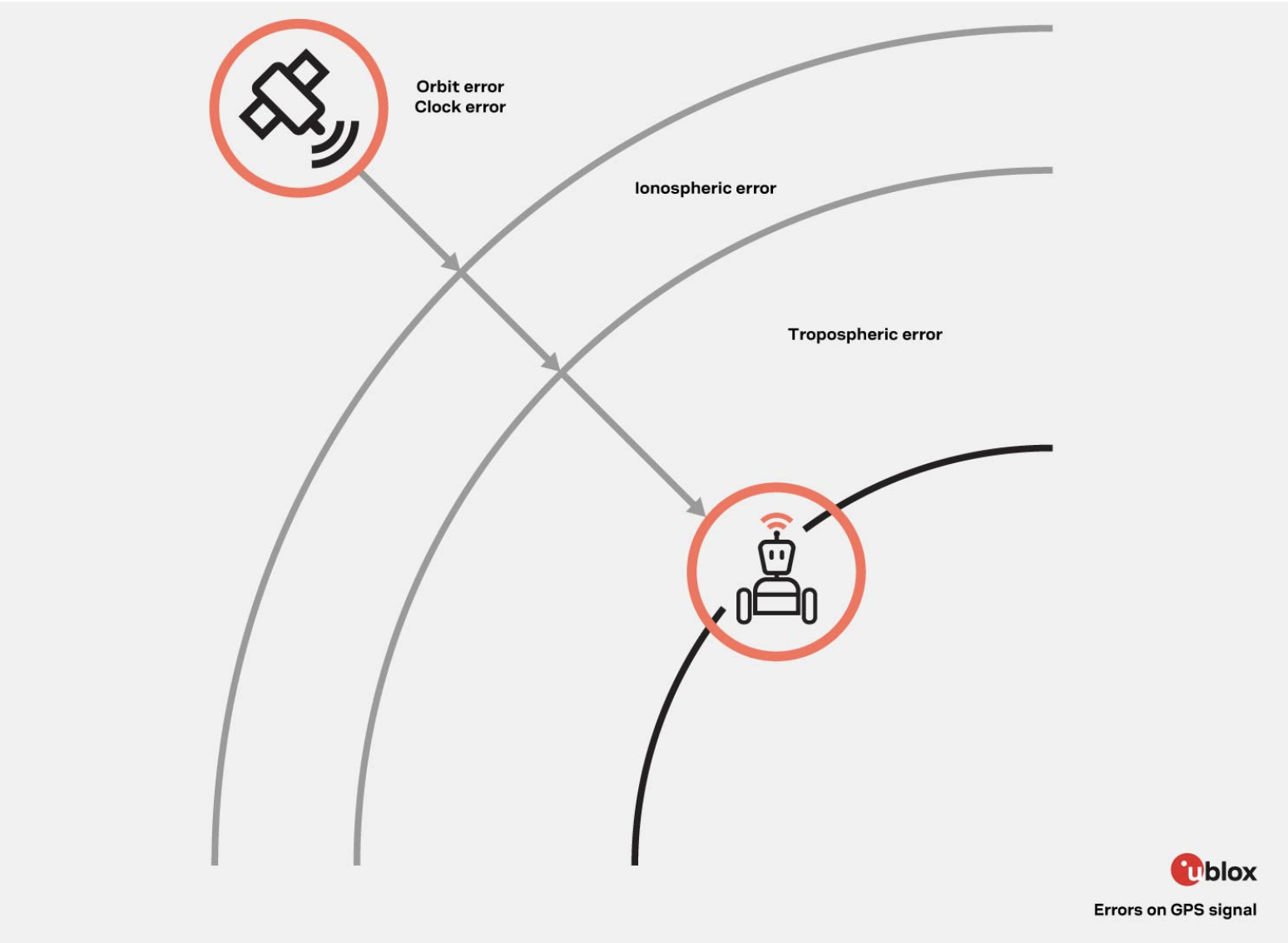
There are several sources of inaccuracies in GNSS positioning. Some of the common sources include:
Atmospheric Delays: GNSS signals can be delayed or distorted as they pass through the Earth's atmosphere. Factors such as ionospheric and tropospheric conditions can introduce errors in the signal propagation, leading to inaccuracies in positioning.
Multipath Interference: Multipath interference occurs when GNSS signals reflect off surfaces such as buildings, trees, or other obstacles before reaching the receiver. These reflected signals can interfere with the direct signals, causing errors in the position calculation.
Satellite Orbit Errors: GNSS satellites have predictable orbits, but there can be slight deviations from their ideal paths. Inaccuracies in satellite orbit determination or clock synchronization can introduce errors in the positioning calculations.
Receiver Errors: GNSS receivers themselves can introduce errors due to imperfections in the receiver hardware or software. These errors can arise from signal processing, noise, or calibration issues within the receiver system.
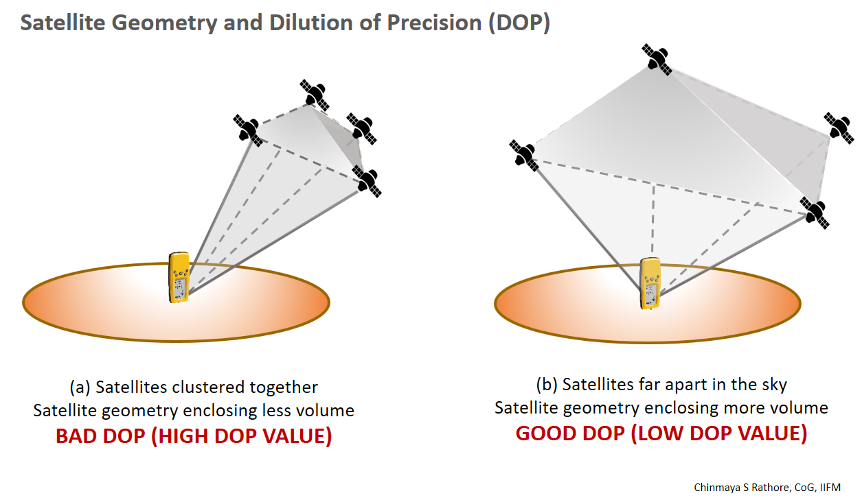
Geometric Dilution of Precision (GDOP): GDOP is a measure of the geometric configuration of satellites relative to the receiver. Poor satellite geometry, such as having satellites clustered in one area of the sky, can result in higher positioning errors.
Signal Obstruction: Buildings, trees, and other physical obstructions can block or weaken GNSS signals, leading to reduced signal quality and increased positioning errors. However, GNSS signals are not affected by clouds, fog, or even rain. The frequencies were specifically chosen to propagate through these weather events and provide accurate data in any weather or climate.
Ephemeris and Clock Errors: The precise information about satellite positions (ephemeris) and satellite clocks is continuously transmitted to receivers. However, errors in the ephemeris data or satellite clock synchronization can impact the accuracy of GNSS positioning.
Types of Corrections
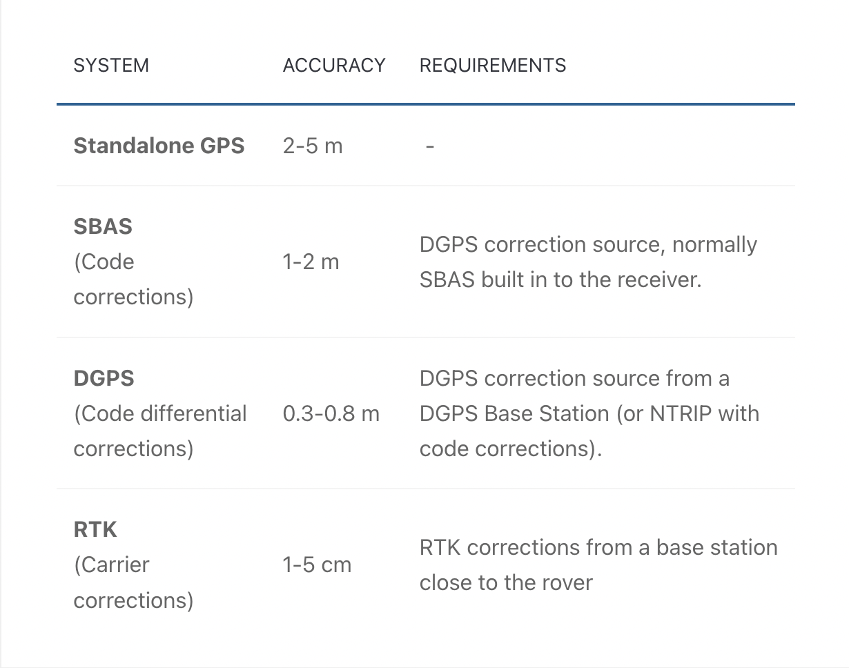
To mitigate these inaccuracies, various techniques are employed, including differential GNSS (DGNSS) that uses reference stations to provide correction data, satellite-based augmentation systems (SBAS) that broadcast correction signals, and real-time kinematic (RTK) positioning that uses carrier-phase measurements for higher accuracy.
DGNSS
Differential correction is a technique used in GNSS positioning to improve the accuracy of measurements. It involves comparing the measurements from a reference station, known as the base station, with those from a roving receiver. By calculating the differences between the two sets of measurements, correction data is generated and applied to the roving receiver's measurements, resulting in improved accuracy.
The base station is a stationary GNSS receiver with a known position. It continuously tracks the signals from the same satellites that the roving receiver is observing. The base station's measurements, referred to as reference measurements, are collected and processed. These measurements are then transmitted to the roving receiver, typically through a radio link or other means of communication.
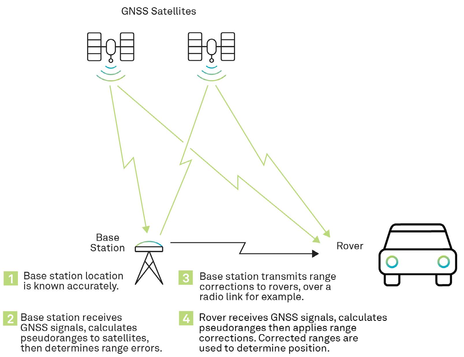
At the roving receiver, the received correction data is applied to the corresponding measurements. This correction compensates for various errors and inaccuracies present in the measurements, by subtracting the correction data from the roving receiver's measurements, the accuracy is enhanced, resulting in improved positioning accuracy.
Differential correction can be performed in real time or as post-processing after data collection. In real-time differential correction, the correction data is transmitted to the roving receiver immediately, enabling instantaneous improvements in accuracy. Post-processing differential correction involves collecting data with both the base station and the roving receiver and then processing the data offline to generate precise correction data that is applied retrospectively.
Real-Time Kinematic (RTK) Correction
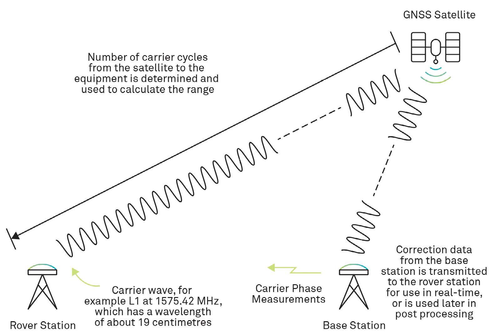
RTK is a type of differential correction to that involves measuring the carrier phase of GNSS signals instead of the data within them. By analyzing the carrier phase, RTK can mitigate errors caused by atmospheric delays and other sources, leading to centimeter-level positioning accuracy in real time.
RTK works by establishing a fixed base station with a known position and a mobile rover receiver whose position is to be determined. The base station receives signals from GNSS satellites and calculates the precise phase measurements. These measurements, along with the known position of the base station, are transmitted to the rover receiver in real time. The rover receiver then compares its own carrier phase measurements with the corrected phase measurements received from the base station, enabling it to compute highly accurate positioning information.
However, RTK does have a few limitations. It requires a real-time communication link between the base station and the rover receiver, which may limit its range of operation. In areas with limited or no communication coverage, the RTK technique may not be feasible. Second, RTK positioning is sensitive to signal obstructions and multipath interference. Buildings, trees, or other obstacles that block or reflect signals can introduce errors in the carrier phase measurements, impacting the accuracy of RTK positioning. Additionally, RTK can be affected by ionospheric and tropospheric conditions, and inaccuracies in the base station position or satellite ephemeris data can also degrade its performance.
Furthermore, RTK requires precise synchronization of clocks between the base station and the rover receiver. Any discrepancies in clock synchronization can introduce errors in the carrier phase measurements, affecting the accuracy of the positioning solution. Additionally, RTK equipment can be relatively expensive and requires careful setup and calibration to achieve optimal performance.
Despite these challenges and limitations, RTK remains a valuable technique for achieving highly accurate real-time positioning in applications such as surveying, precision agriculture, and construction. It continues to be an essential tool for applications that demand centimeter-level accuracy and require precise positioning information in real time.
Satellite Based Augmentation System (SBAS)
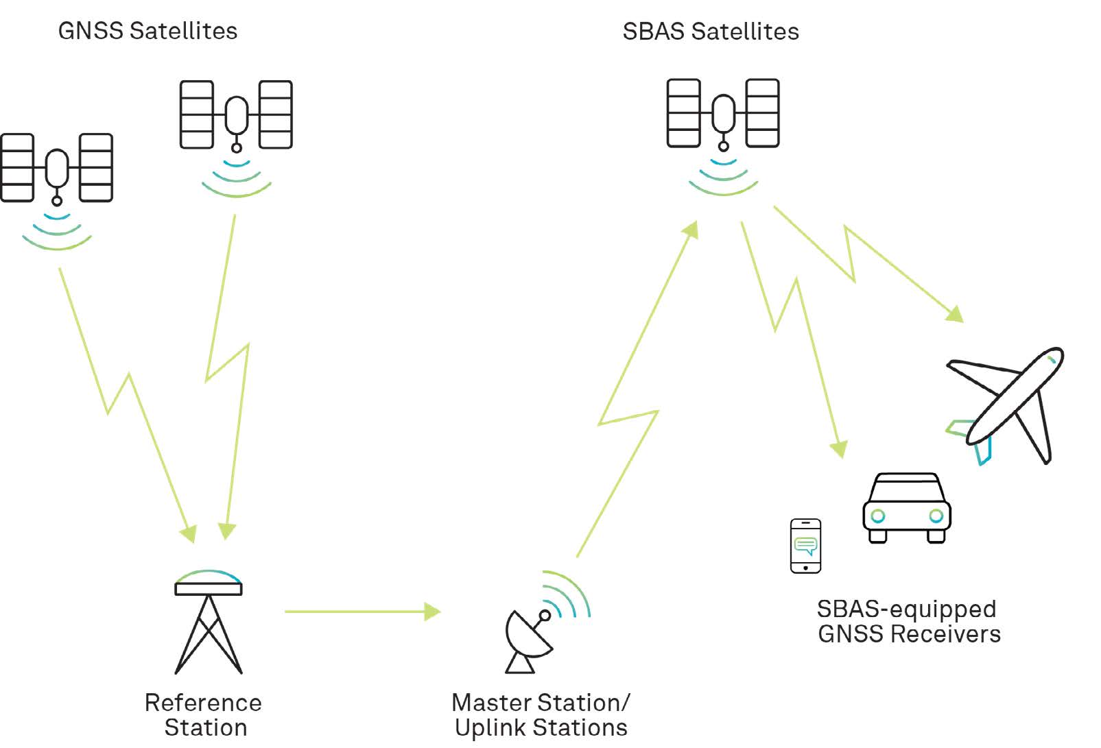
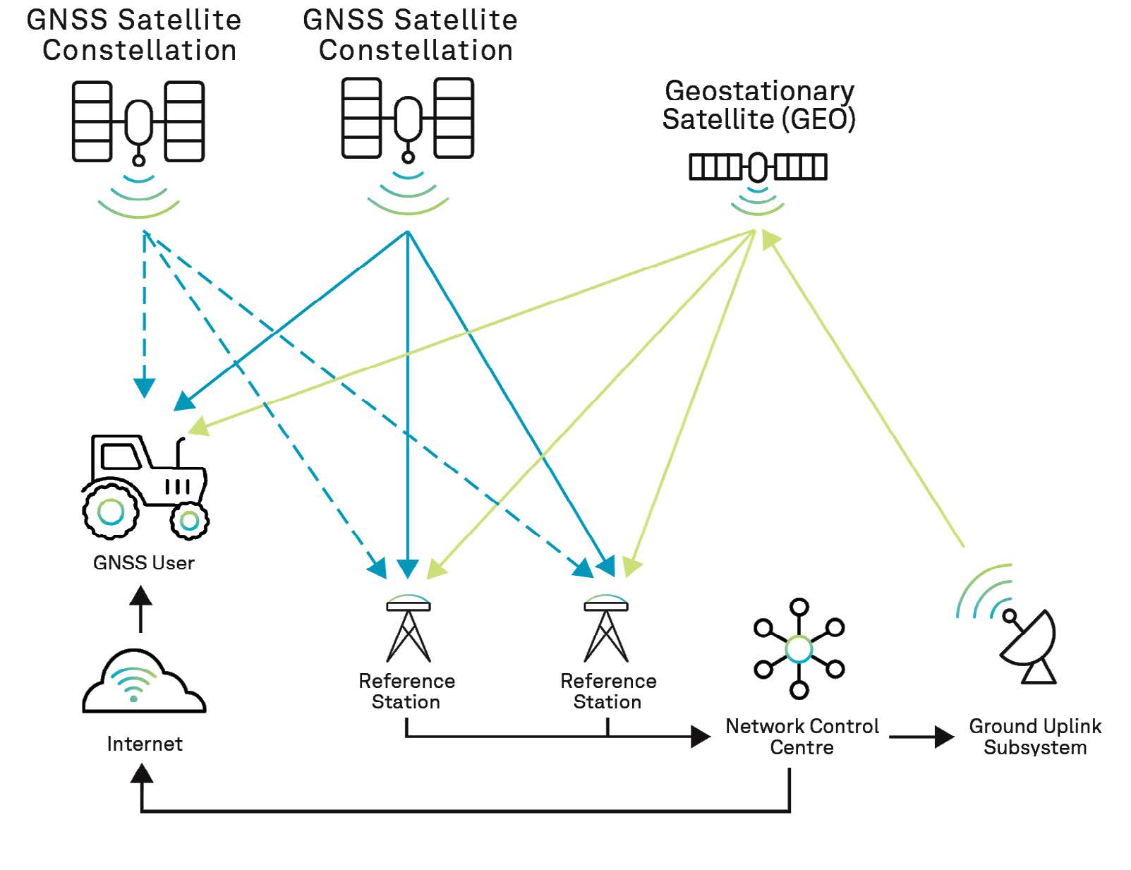
SBAS stands for Satellite-Based Augmentation System. It is a regional or global system that utilizes additional satellites and ground-based infrastructure to augment and enhance the accuracy, integrity, and availability of GNSS signals. SBAS systems are designed to provide improved positioning accuracy, integrity monitoring, and availability of GNSS signals for various applications.
The primary purpose of an SBAS is to mitigate errors and enhance the performance of GNSS by providing correction and integrity information. These systems are typically operated by governmental or collaborative entities and cover specific geographical regions. Different regions have their own SBAS systems; Wide Area Augmentation System (USA), European Geostationary Navigation Overlay Service (Europe), Multi-functional Satellite Augmentation System (Japan), and the Indian Satellite-Based Augmentation System (India) are a few. These are all operated by their respective region's governing body for aviation.
SBAS systems use a network of reference stations, satellite links, and ground-based master stations to collect GNSS measurements, compute correction data, and broadcast them to user receivers via geostationary satellites. GNSS receivers equipped with SBAS capability receive these correction messages, which enable them to enhance their accuracy and reliability.
Emerging Technologies and Advancements
Precise Point Positioning (PPP) is a technique used in GNSS positioning to achieve high-precision and accurate positioning solutions. Unlike traditional differential techniques that rely on correction data from nearby reference stations, PPP leverages a global network of reference stations distributed worldwide. By utilizing precise measurements from multiple GNSS satellites and sophisticated algorithms, PPP enables centimeter-level positioning accuracy without the need for a nearby reference station.
PPP operates by processing the raw GNSS measurements from the user's receiver along with the measurements from the global network of reference stations. The reference station measurements are used to compute correction parameters, such as satellite orbit and clock errors, atmospheric delays, and other systematic errors. These correction parameters are then applied to the user's measurements to improve the accuracy of the positioning solution. PPP takes into account factors such as satellite geometry, atmospheric conditions, and signal propagation delays to achieve precise positioning results.
To implement PPP, a user typically needs access to precise correction data, which is typically provided through satellite-based augmentation systems (SBAS) or Internet-based services. This correction data is transmitted to the user's receiver in real time or can be used for post-processing. The receiver incorporates this correction data along with its own measurements to compute highly accurate positioning solutions. PPP is widely used in applications such as surveying, geodesy, precision agriculture, and scientific research, where high-precision positioning is essential. It offers a robust and globally available solution for achieving accurate and reliable positioning results.
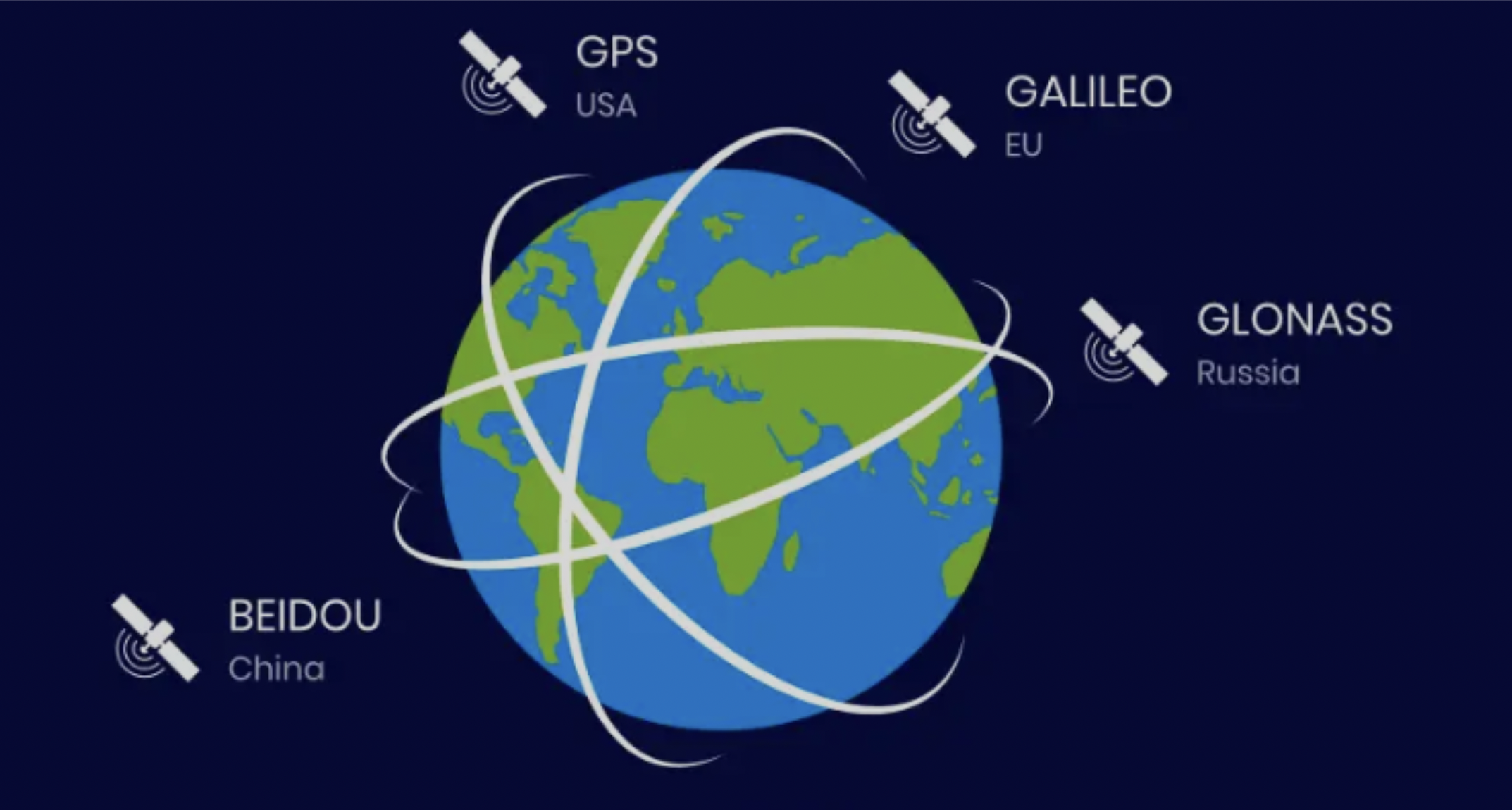
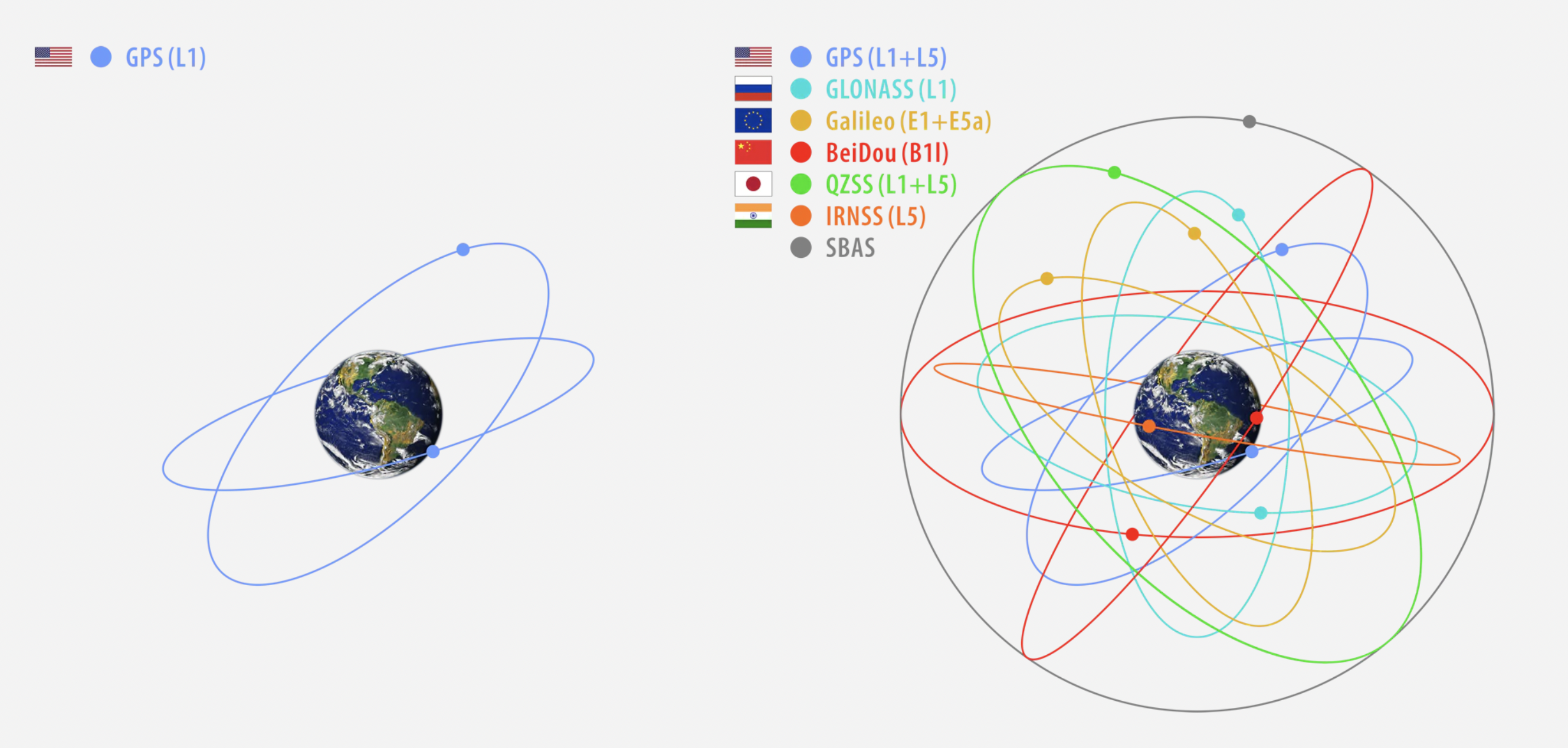
Multi-constellation and multi-frequency GNSS refers to the utilization of signals from multiple satellite constellations and multiple frequency bands in GNSS positioning. Traditionally, GPS (Global Positioning System) has been the primary constellation used for positioning. However, advancements in technology have led to the deployment of additional constellations such as GLONASS, Galileo, and BeiDou, which greatly expand the number of available satellites for positioning.
By incorporating signals from multiple constellations, multi-constellation GNSS improves the availability and reliability of satellite signals. It allows receivers to track satellites from different constellations simultaneously, increasing the number of visible satellites and reducing the risk of signal blockages caused by obstructions or signal interference. This enhances the robustness and accuracy of positioning solutions, particularly in challenging environments such as urban canyons or areas with dense foliage.
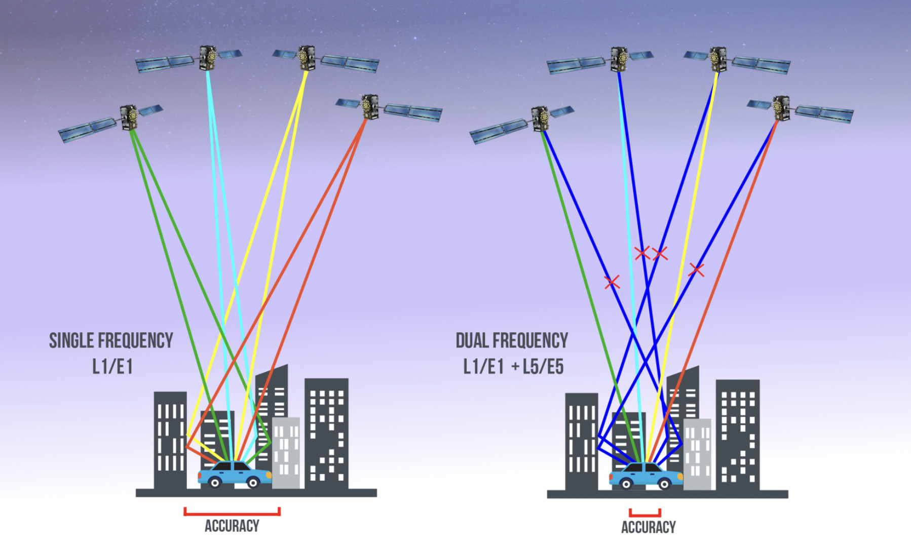
Furthermore, multi-frequency GNSS refers to the reception and processing of signals across different frequency bands. Traditional GPS receivers typically used L1 frequency signals. However, with the introduction of new constellations and signals, development of GNSS receivers that can receive signals on multiple frequencies (such as L1, L2, L5, E1, E5, etc) could be on the horizon. Multi-frequency GNSS offers several benefits, including improved ionospheric error correction and more accurate determination of carrier phase measurements. It helps mitigate the effects of ionospheric delays, which can introduce errors in GNSS positioning, particularly for single-frequency receivers.
Correction data plays a crucial role in integrating with other positioning technologies to enhance accuracy and reliability.
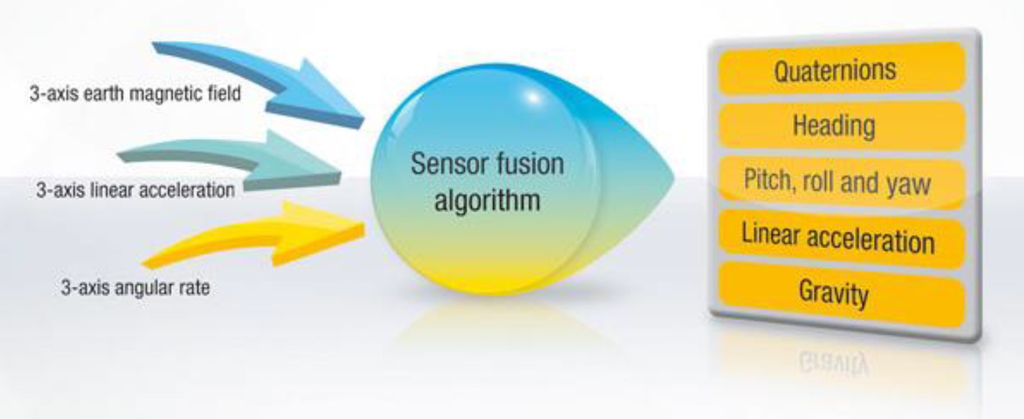
Inertial Navigation Systems (INS): INS combines measurements from inertial sensors (accelerometers and gyroscopes) with GNSS data to provide continuous and accurate positioning information. However, inertial sensors are prone to drift over time. By integrating correction data, such as from PPP or differential techniques, with INS, the drift errors can be corrected, improving the long-term accuracy and stability of the positioning solution.
Sensor Fusion: Correction data can also be integrated with other sensors, such as magnetometers, odometers, or vision-based systems, in sensor fusion approaches. Sensor fusion combines data from multiple sensors to create a more robust and accurate positioning solution. By incorporating correction data, obtained from reference stations or precise GNSS techniques, the accuracy of the fusion solution can be improved, particularly in challenging environments where individual sensors may be prone to errors or limitations.
Integration of correction data with other positioning technologies is typically achieved through appropriate algorithms and data fusion techniques. The correction data is either applied directly to the measurements or used in error modeling and estimation processes to improve the accuracy of the positioning solution. This integration enables users to leverage the strengths of different technologies and enhance the overall performance and reliability of positioning systems in various applications.
Applications of Correction Data
Aviation and Aerospace
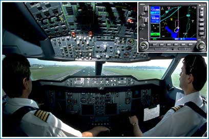
Correction data is crucial in aviation and aerospace industries to ensure accurate and reliable positioning for aircraft and spacecraft. In aviation, GNSS receivers on board aircraft receive correction data, such as those provided by satellite-based augmentation systems (SBAS), to enhance the accuracy of aircraft navigation. This is particularly important during precision approaches and landings, where precise positioning is essential for safe operations. Correction data helps pilots maintain the desired flight path, avoid obstacles, and optimize flight efficiency. In the aerospace industry, correction data is also utilized for precise orbit determination of satellites, allowing for accurate satellite positioning, attitude control, and precise payload deployment.
Maritime Navigation
Correction data is widely used in maritime navigation for improving the accuracy and safety of vessels at sea. Ships equipped with GNSS receivers receive correction data, typically through radio or satellite links, to correct for errors in satellite signals and enhance the accuracy of position fixing. This is particularly important in marine transportation, where precise positioning is crucial for safe navigation, collision avoidance, and efficient route planning. Correction data helps vessels navigate through challenging marine environments, such as congested waterways, areas with signal blockages, or regions with strong tides or currents.
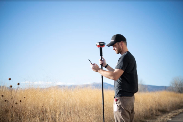
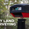
Surveying
Correction data plays a vital role in surveying and mapping applications, where high-precision positioning is required. Surveyors use GNSS receivers to collect precise measurements for mapping, land surveying, construction projects, or even mapping uncharted caves. By integrating correction data, such as real-time kinematic (RTK) or post-processed differential correction data, surveyors can achieve centimeter-level positioning accuracy. Correction data helps compensate for various error sources, including atmospheric delays, satellite clock errors, and multipath effects. This ensures that surveying and mapping data is highly accurate and reliable, enabling the creation of detailed and precise maps, models, and infrastructure plans.
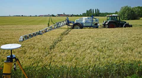
Agriculture
In precision agriculture, correction data is used to optimize farming operations and increase crop yields. GNSS receivers integrated into agricultural machinery, such as tractors or drones, receive correction data in real time, allowing for precise positioning of the equipment. This enables farmers to perform precise tasks, such as planting, spraying, or harvesting, with high accuracy. Correction data helps farmers minimize overlaps, reduce input waste, and apply fertilizers or pesticides with precision. By leveraging correction data, precision agriculture practices can improve resource efficiency, reduce environmental impact, and optimize crop productivity.
Autonomous Vehicles
Correction data is also critical for the successful operation of autonomous vehicles, including self-driving cars, drones, and robotics. Autonomous vehicles rely heavily on accurate and reliable positioning information for navigation, obstacle detection, and path planning. GNSS receivers in autonomous vehicles use correction data to enhance positioning accuracy, particularly in challenging urban environments or areas with signal interference. Real-time correction data, delivered through cellular networks or Internet-based services, allows autonomous vehicles to maintain accurate positioning, enabling safe and efficient autonomous operations. Correction data ensures that autonomous vehicles can accurately navigate complex road networks, avoid collisions, and make informed decisions based on reliable positioning information.
Correction data plays a vital role in enhancing the accuracy and reliability of GPS positioning. By providing information to mitigate errors and improve satellite measurements, correction data enables precise positioning in various challenging environments such as urban areas, dense foliage, and signal-obstructed regions. The integration of correction data has revolutionized industries such as aviation, maritime navigation, surveying, precision agriculture, and autonomous vehicles, enabling safer operations, increased efficiency, and improved outcomes.
Looking ahead, the future of correction data holds promising prospects for further advancements. As technology continues to evolve, we can expect improvements in the availability, accuracy, and delivery methods of correction data. Advancements in multi-constellation and multi-frequency GNSS systems, along with the integration of additional sensor technologies, will contribute to even more precise and reliable positioning solutions. Moreover, the growing utilization of cloud computing, machine learning, and artificial intelligence opens doors for advanced algorithms and models that can enhance the processing and utilization of correction data, further improving positioning accuracy and reliability.
Further Resources
- NOAA's GPS Tutorial
- The European Space Agency's deep dive into GNSS data delivery protocols and data formats.
- Novatel's An Introduction To GNSS is a robust online resource with tons of information on all things GNSS and signal processing.
- Check out how you can start using RTK on your own at sparkfun.com/rtk
- Learn more about GPS basics and how to use it in your own projects at sparkfun.com/gps
Take a look at our surveyor line that uses RTK correction data:
And check out our products that use RTK:
We also have lots of blog posts about RTK technology:
As well as tutorials that show you exactly how to start utilizing the GNSS in your own work:
What is GPS RTK?
Learn about the latest generation of GPS and GNSS receivers to get 14mm positional accuracy!
GPS Geo-Mapping at the Push of a Button
Let's ramp up our GPS tracking skills with KML files and Google Earth. We'll make a tracker that logs location and allows us to visualize our steps with Google Earth.
Setting up a Rover Base RTK System
Getting GNSS RTCM correction data from a base to a rover is easy with a serial telemetry radio! We'll show you how to get your high precision RTK GNSS system setup and running.
How to Build a DIY GNSS Reference Station
Learn how to affix a GNSS antenna, use PPP to get its ECEF coordinates and then broadcast your own RTCM data over the internet and cellular using NTRIP to increase rover reception to 10km!
Using RTK in a project? Have some experience with correction data? We want to hear about it! Share in the comments, or find us on Twitter @sparkfun, or let us know on Instagram, Facebook or LinkedIn.


Another interesting read by Redacted! In 2023, we take this technology for granted - it’s in our cars, our phones, our watches, our golf carts - everywhere! Thanks for another educational experience!!